Week 9 - Challenge 1 - Base Bracket Design
Image of Draft anslysis & colour scale varient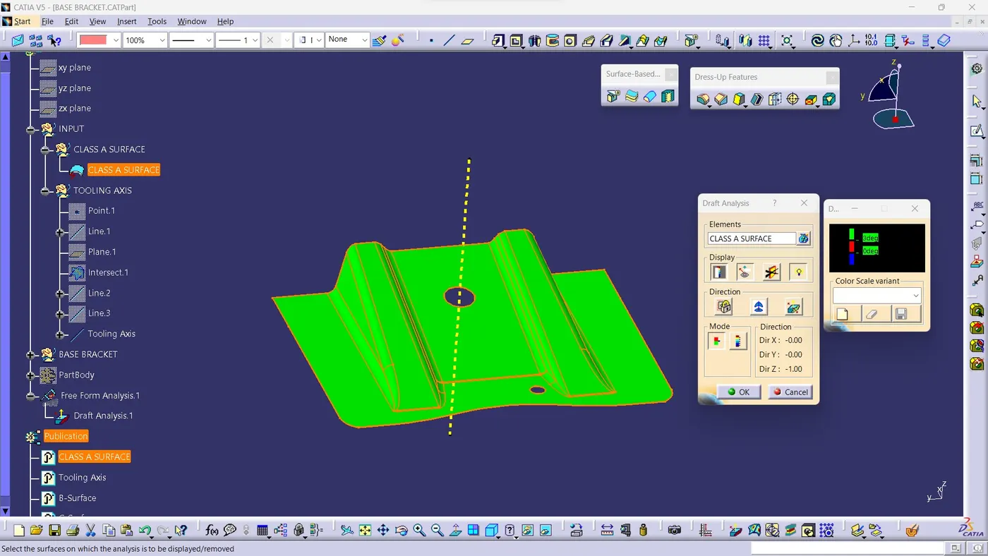
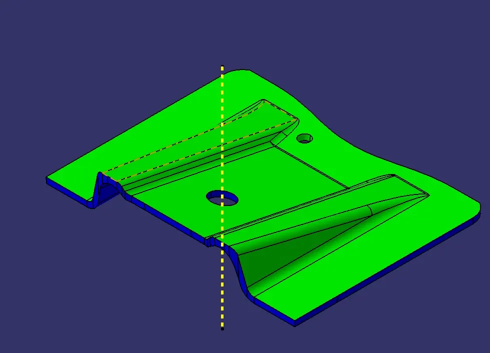
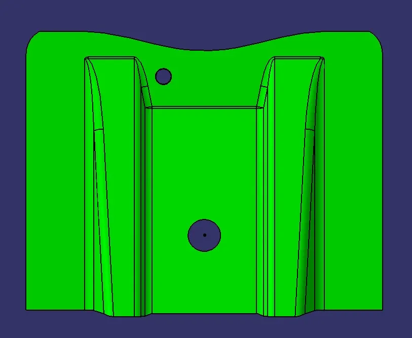
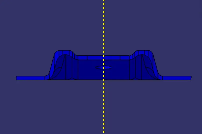
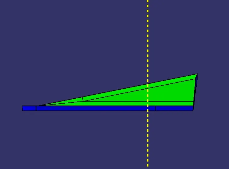
Solid Model
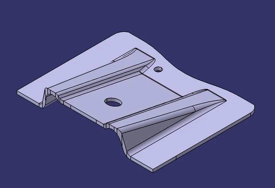
iosmetric view
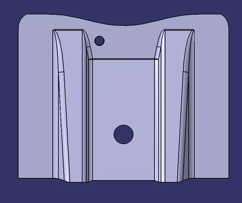
Top View
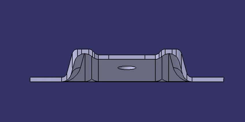
side view
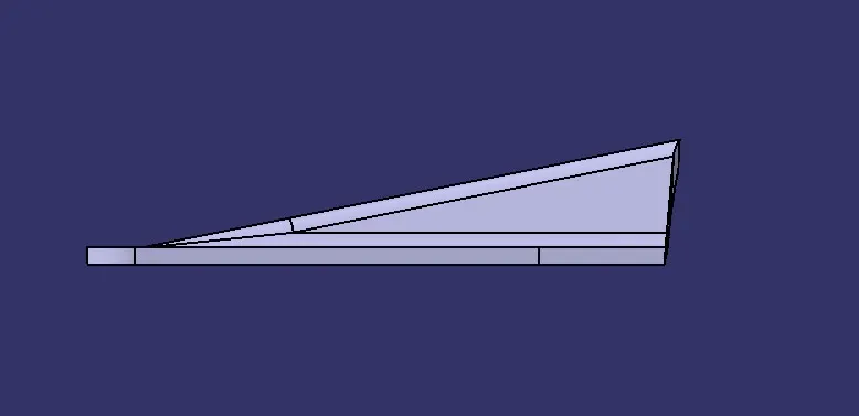
front view
Report on Draft Analysis
Initially, the class The specified surface is examined for surface continuity and any gaps between edges are identified. The tooling axis is then determined. For this, first we should assume which direction is going to be suitable for tooling.Next, a mid-section of the class-A surface is taken and lines are created collinear to the lines which are on the inclined face of the ribs. After that, a line is drawn that represents the angle bisector of the lines mentioned above. Thus the obtained line is the Tooling axis.