Wiring harness design in CATIA V5 - 3D modeling Week 5 & 6 Challenge
Aim: To route the given harness layout in the Electrical Workbench.
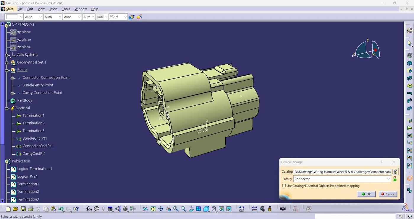
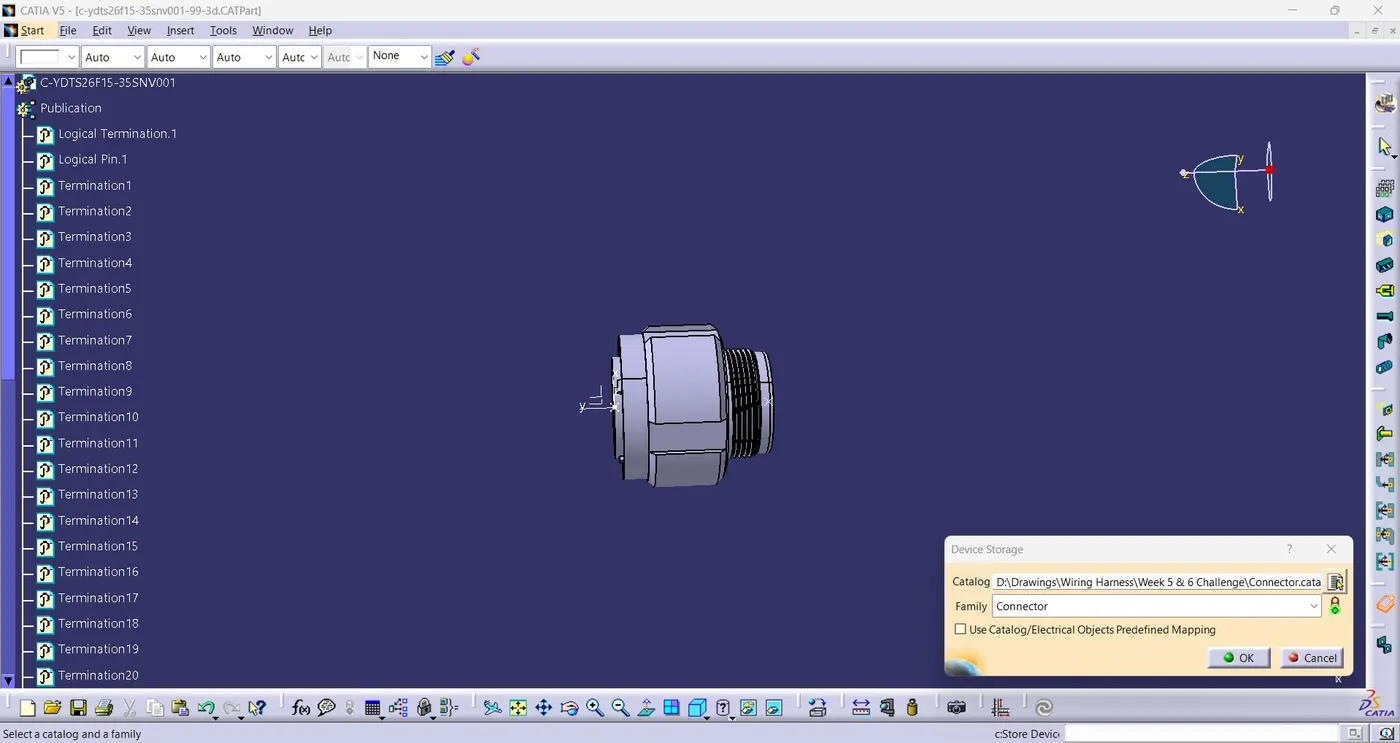
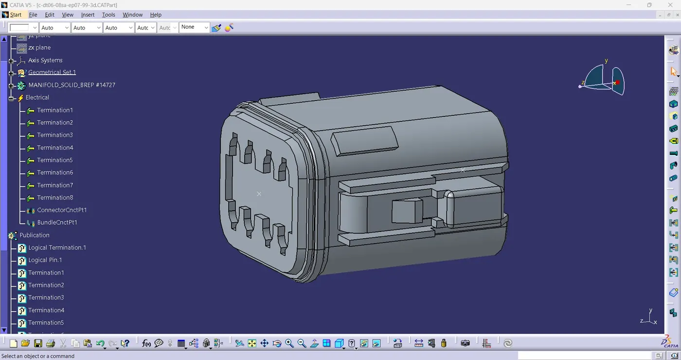
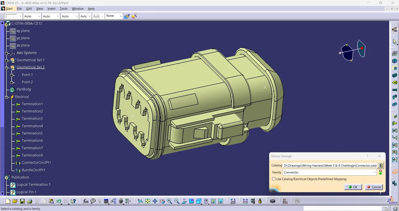
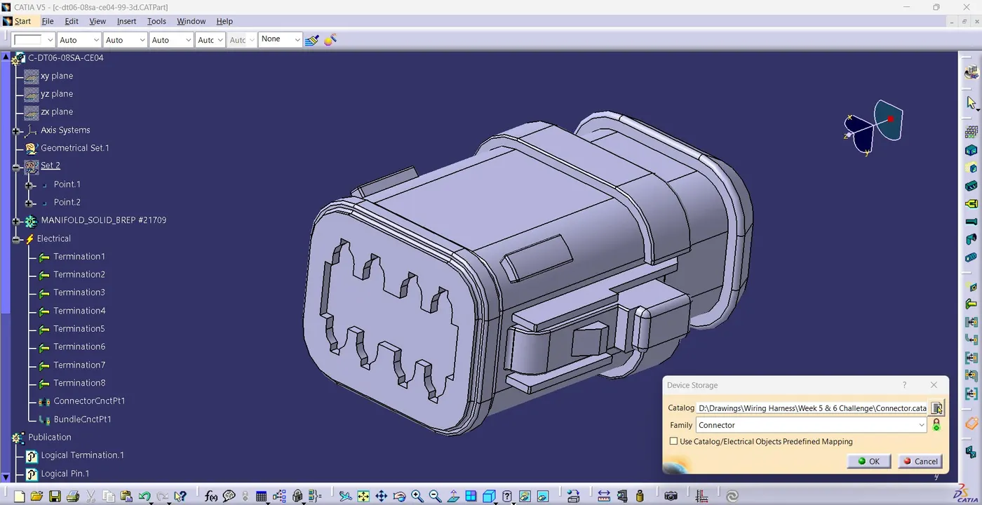
To route the given harness layout, first and foremost thing is to download the 3D CAD data of the connectors. There are 2 harnesses given as Harness A and B. So we have to download each connector for both harnesses, define them electrically and save them into a catalogue for connectors. The following images shows the individual connectors for both the harnesses:
For Harness A, the following connectors are used:
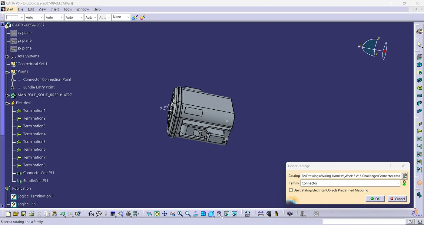
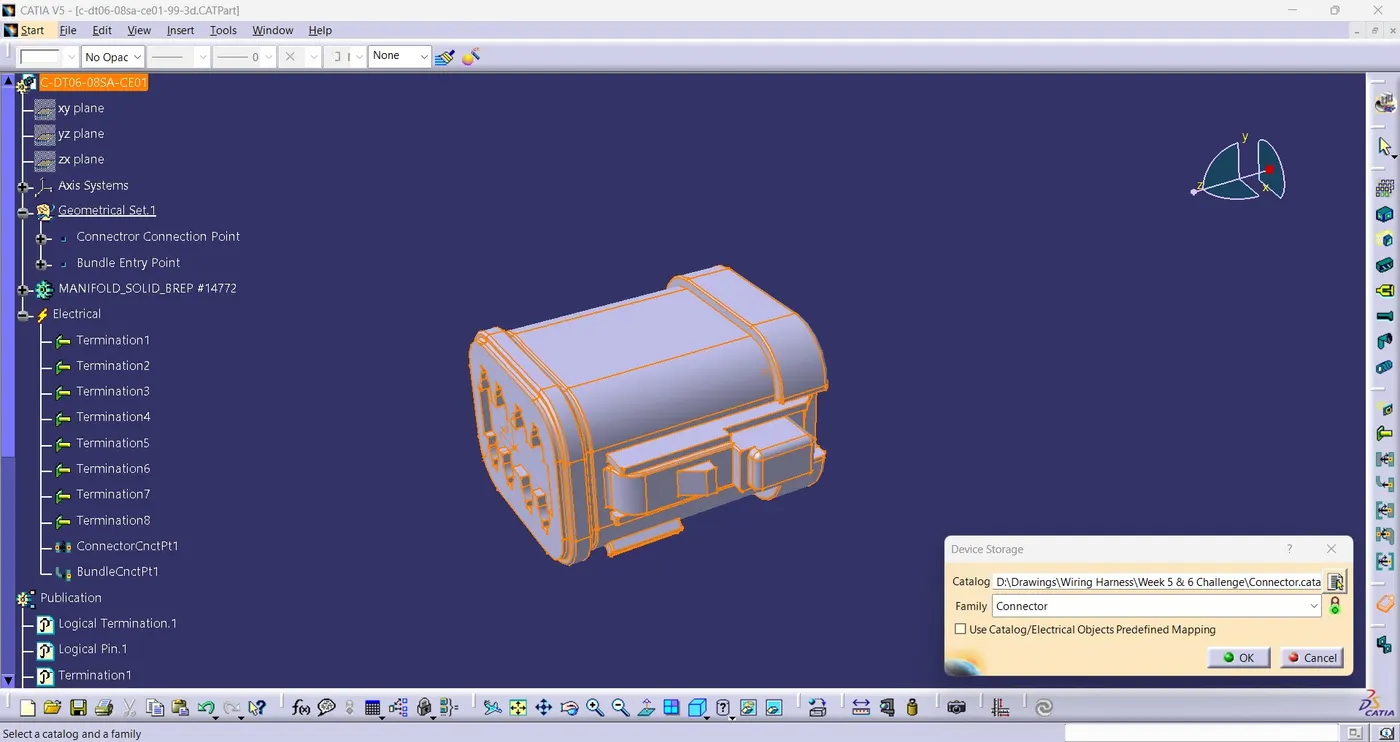
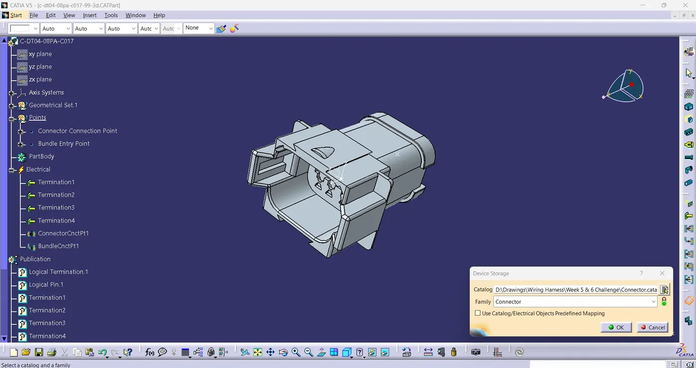
For Harness B, following
connectors are used:
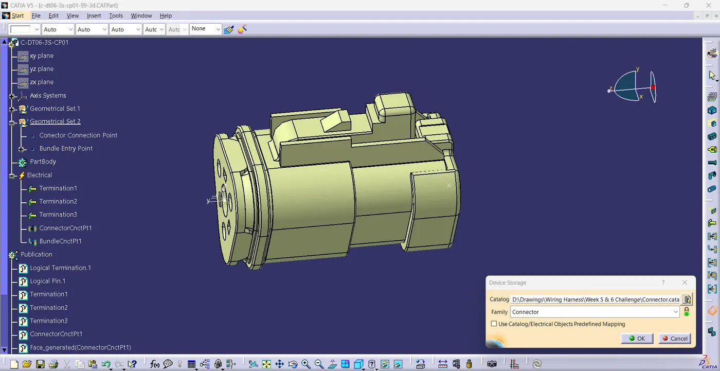
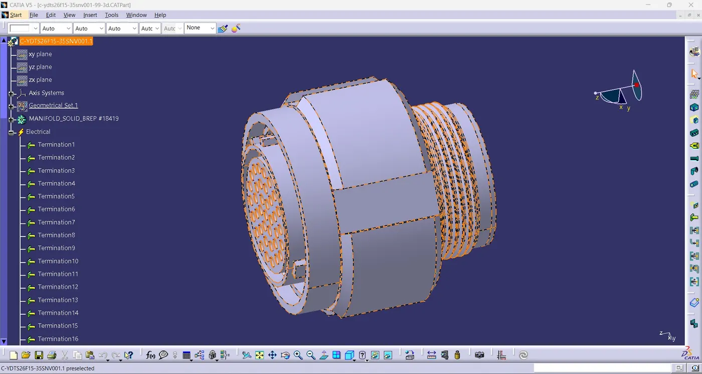
After defining the connectors electrically, we can continue towards harness routing.
First a product file named Harness Assembly is created. Then Harness A and Harness B are created as its sub products.
For Harness A, the connectors are added into the assembly and positioned appropriately. Then in the electrical harness assembly workbench, the geometrical bundle is electrically defined as shown in the figure below:
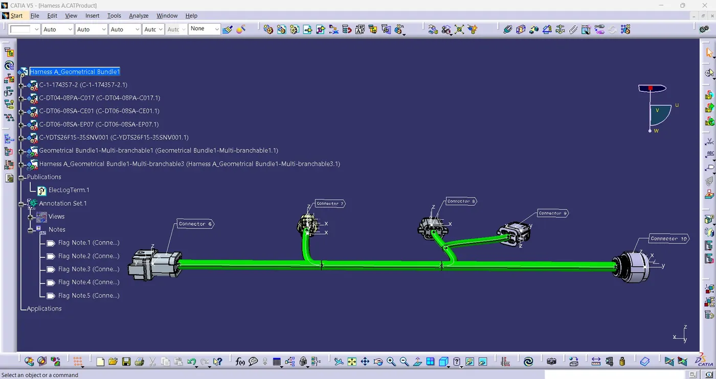
10mm diameter is given for the main
harness bundle and 8mm diameter is given for sub branches.
The bundle continuity is checked
and results obtained are positive as the list for unconnected/unlinked branches
was empty. Snapshot of the search is shown below:
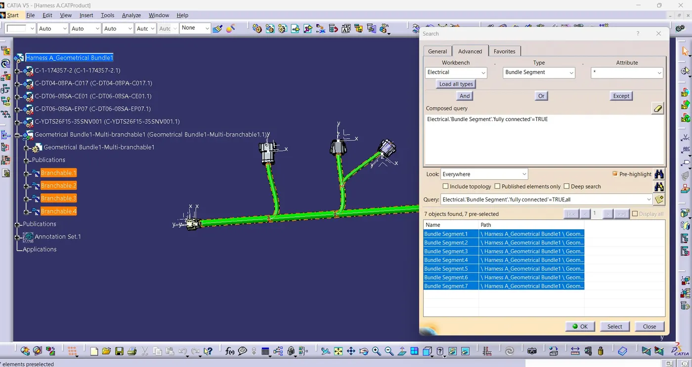
For Harness A, no bundle
warnings were reported. Further to make the design more accurate to the given
diagram, using tangent management, the routing had been modified as shown in the
figure below:
For Harness B also, the same steps
are followed as what done for Harness A. The corresponding images are shown
below:
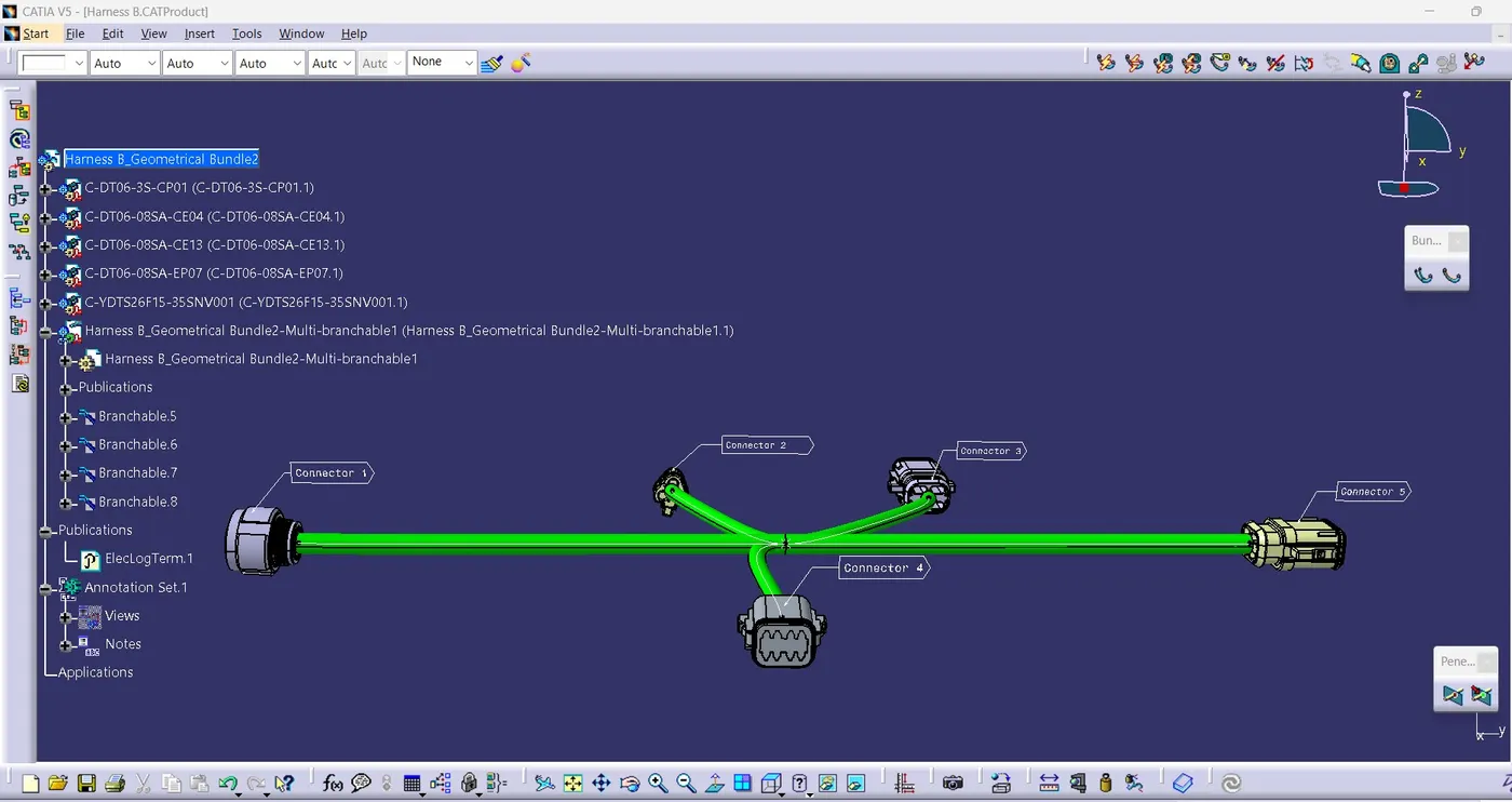
While creating the harness bundle, following bundle warning was occurred. This can be rectified using different methods. The simplest method is to reposition the overhead connectors to some little distance above, so that the calculated bend radius meets the par. After rectifying the errors, the Harness B is developed.
10mm diameter is given for the main
harness bundle and 7mm diameter is given for sub branches.
The bundle continuity is checked
and results obtained are positive as the list for unconnected/unlinked branches
was empty. Snapshot of the search is shown below:
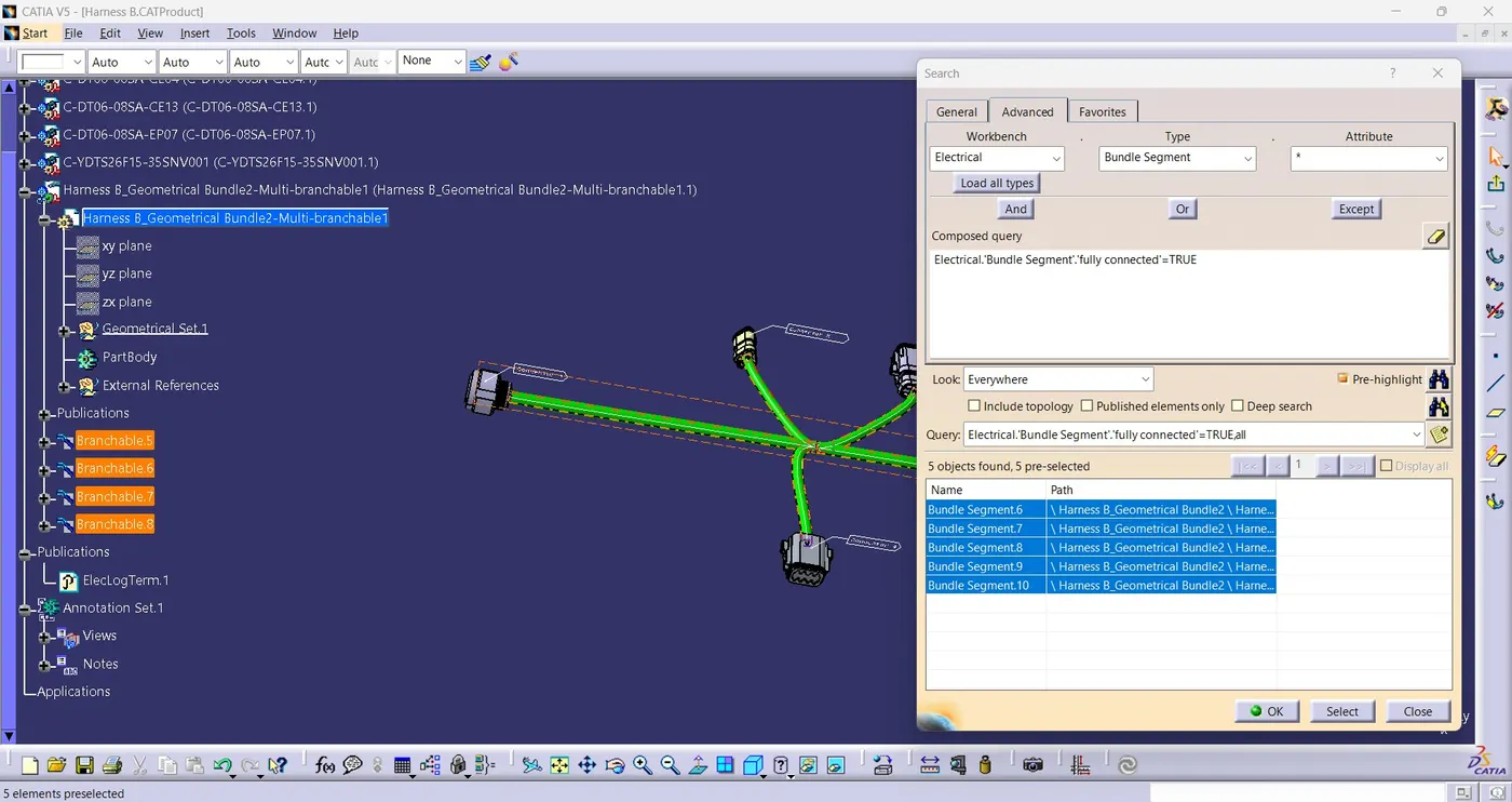
Now both the harness assemblies are taken into the main assembly.
In the electrical assembly design workbench, both harnesses are connected together using connect command. The figure is shown below:
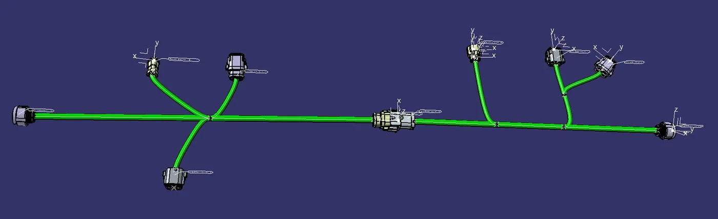
Using Generate CATPart from Product command in Mechanical Assembly Workbench, the CATPart file of the assembly is created.
Annotations are created for each harness bundles as shown below:
The following figure shows the
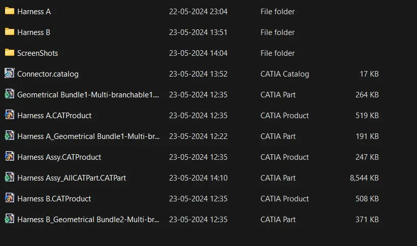
attached files with this challenge: