Project 1
Aim:- To route the Wiring harness
on given engine and prepare flattened view drawing in CATIA V5.
Modeling:-
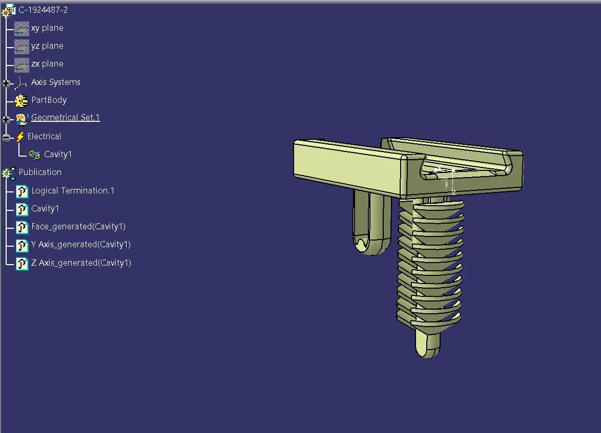
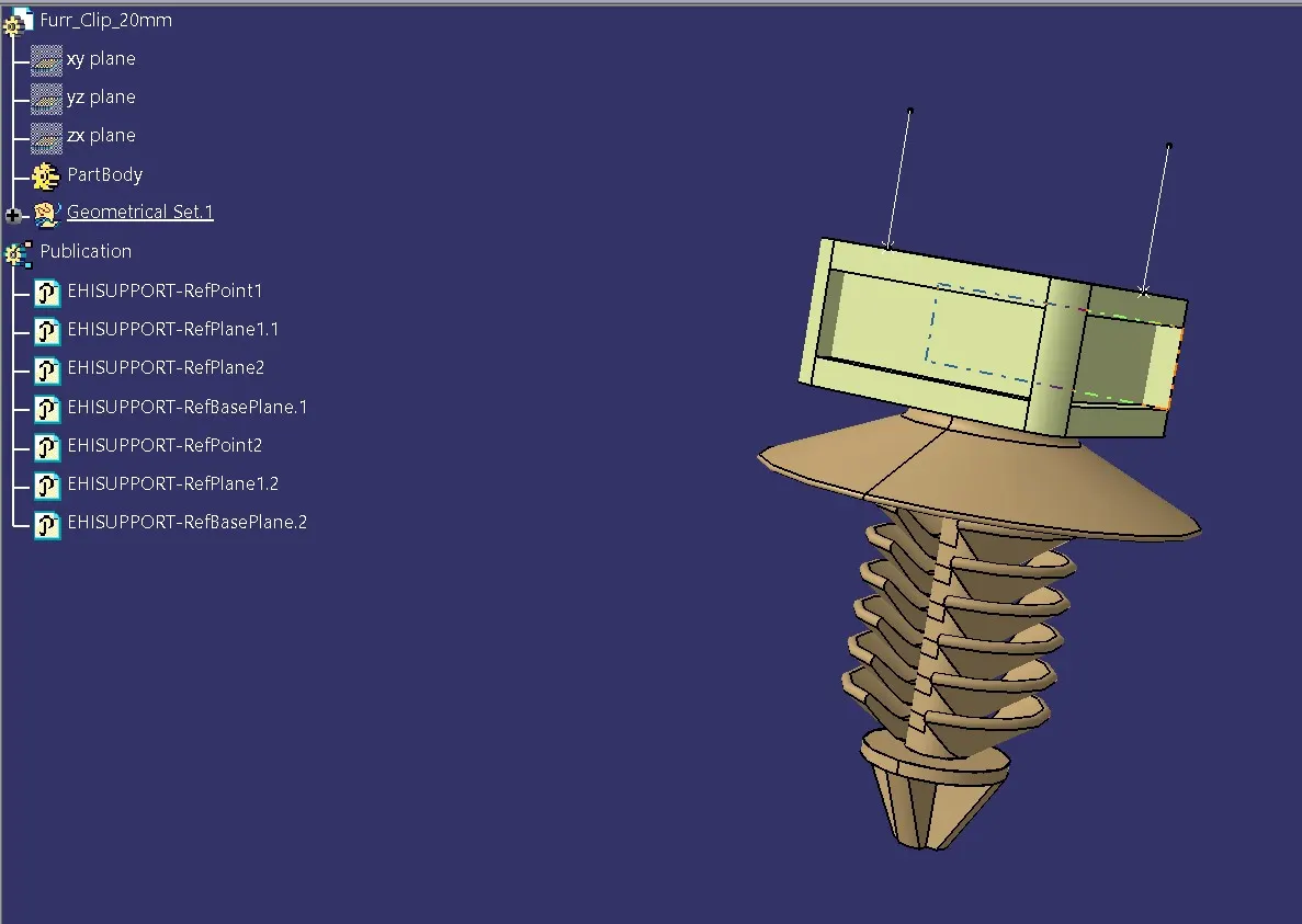
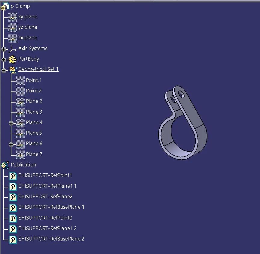
To start with, the and first and foremost is to download the 3D cad data from the given link and www.te.com.Then, the parts (connectors, clips and clamps) are to be electrically defined and stored in appropriate catalogues (in catalogues for connectors as well as for clips and lamps). These are done as shown below:
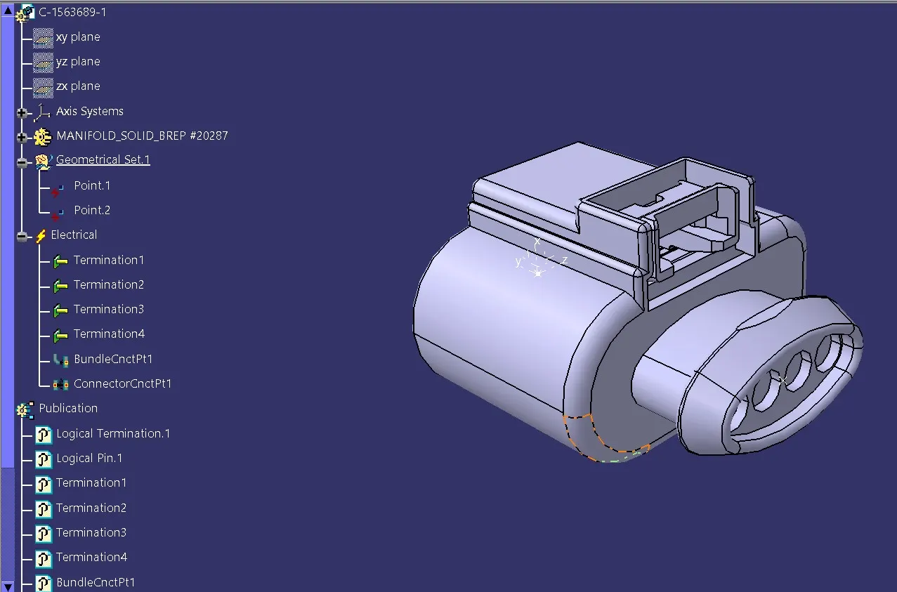
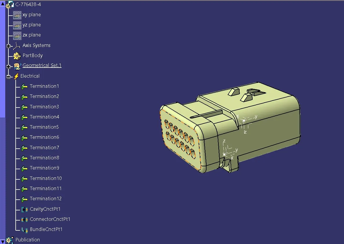
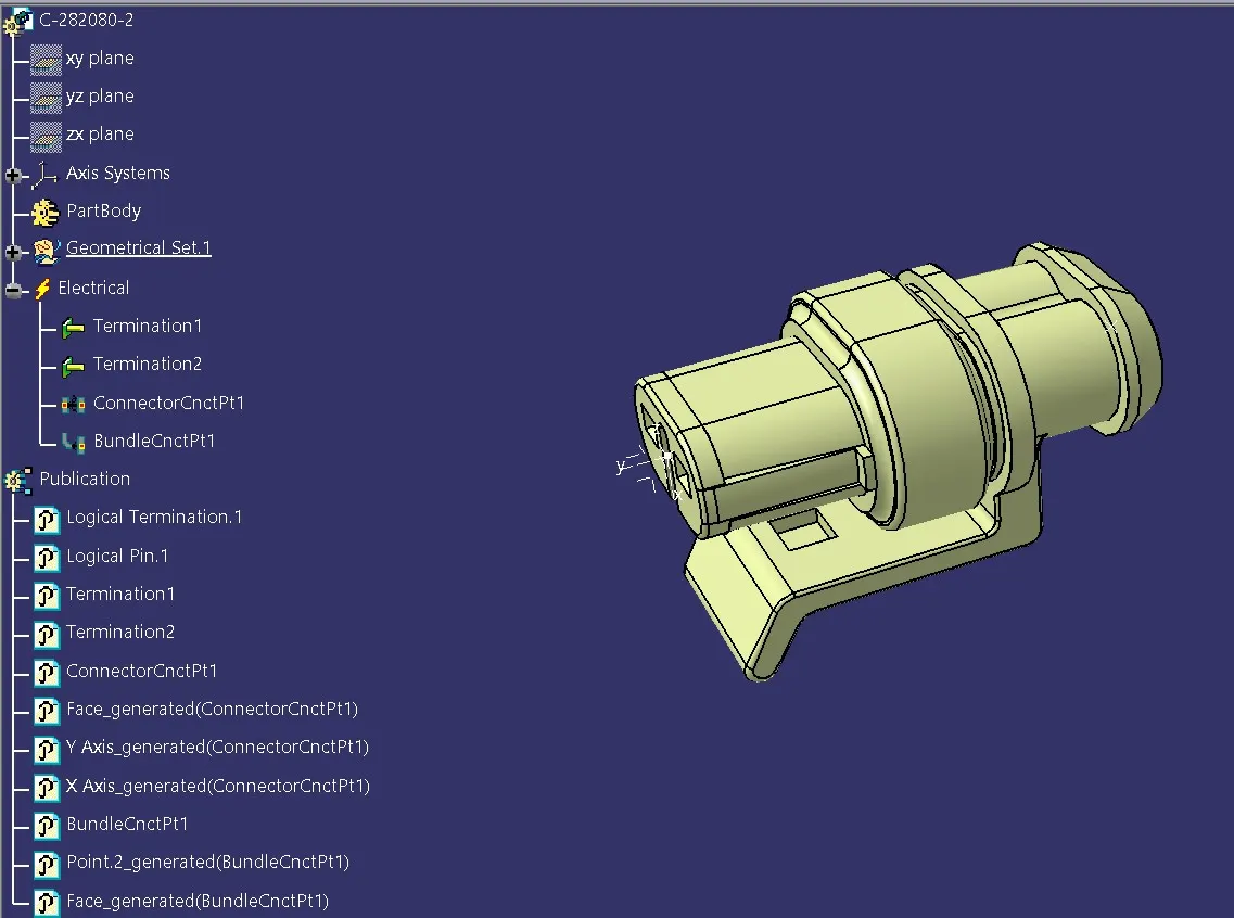
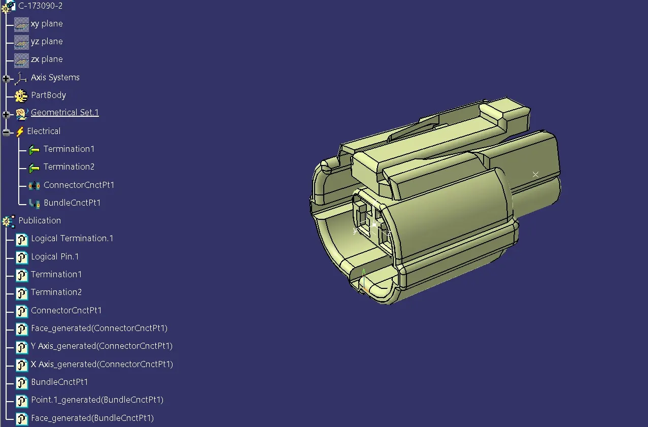
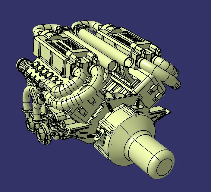
The engine part file is also downloaded from the link. A product file for Engine Harness Context assembly is created. In that the engine product as well as geometrical bundle is added for wiring harness routing as shown below:
Now we have to place connectors for injectors, camshaft senores, transmission sensor, neutral sensor and engine coolant temperature sensor on the engine. For injectors, 4 pole connectors are used which are in a total of 16. For Camshaft sensors also, 4 pole connectors are used which are which are 4 in number. The connectors used for coolant temperature sensor, neutral and transmission sensor, 2 pole connectors are used. This is done as shown below:
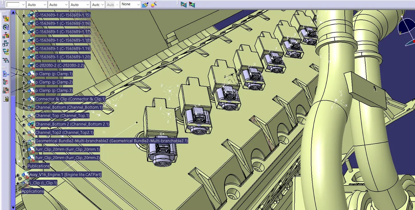
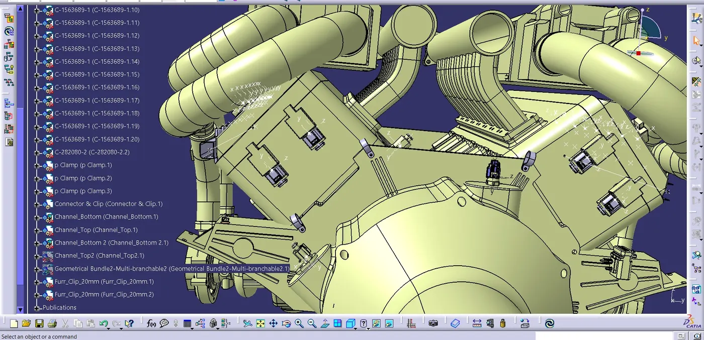
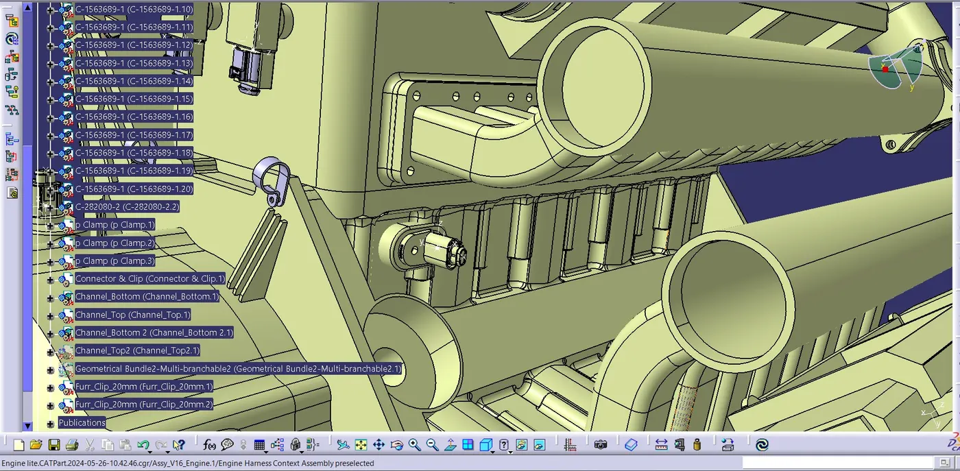
Thus connectors are put in place.
Now, we can assume a convenient position for the interconnection of chassis wiring harness with engine wiring harness. For the interconnection to be positioned, a land is required, for that purpose a 'L' bracket is created and positioned as shown below:
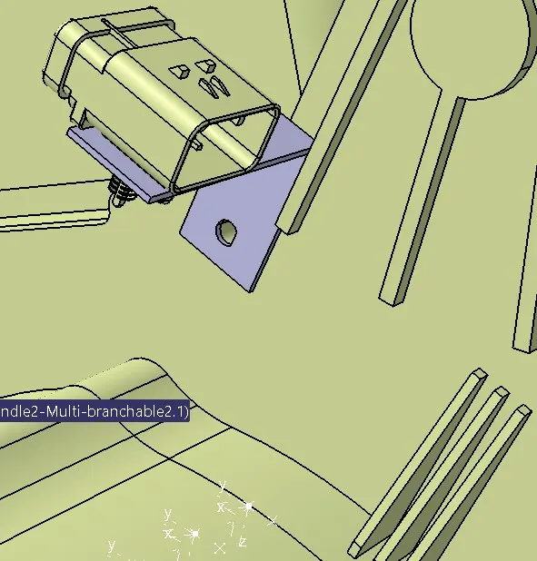
As a part of wiring harness planning, some P
Clips are added for better arrangement of harness bundles. However they may be
manipulated if required.
For injector connectors, guiding channels are to be
provided to the harness bundle, to ensure safe and smooth continuity of the
bundle. For that, guiding channels are created as bottom and top covers, and
put in place as shown in the below figure. The fixations are to be ensured
because there are no provisions for fixation on the side face as per now.
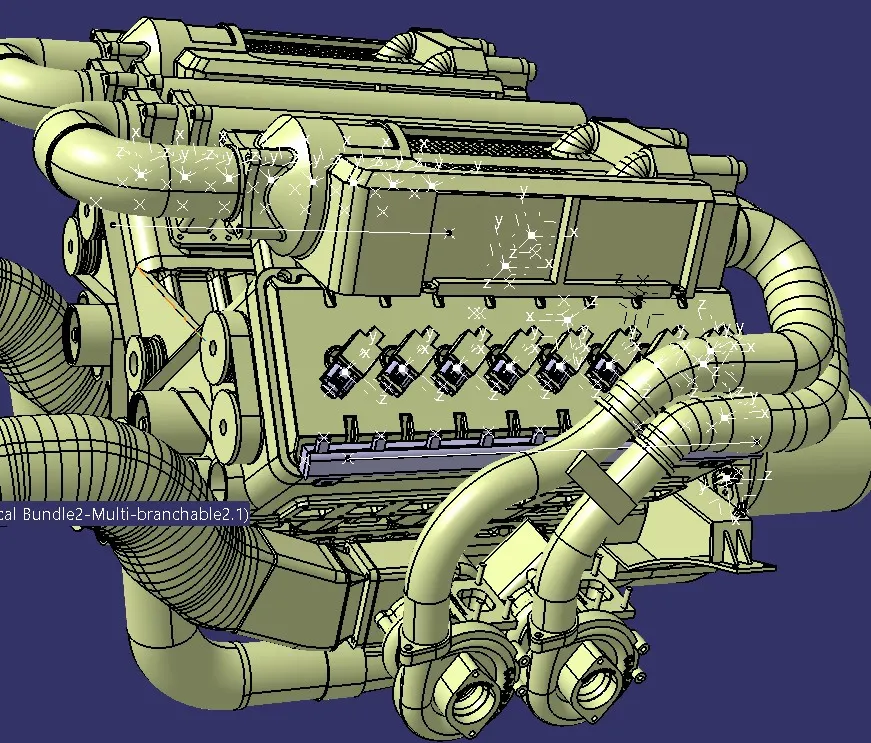
Before starting routing, some furr tree
clips are also added in order to ensure smooth continuity of the harness
bundle.
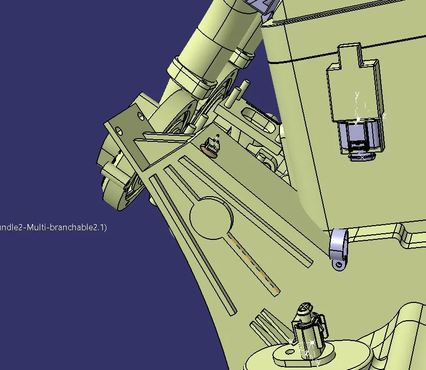
The wiring harness routing have been done as
shown below. Necessary arrangements have made on the placements of clips and
clamps for proper routing:
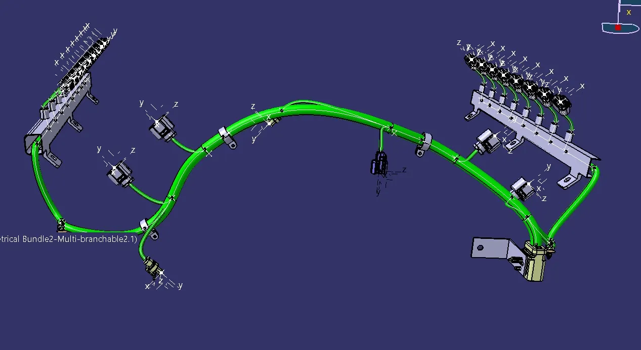
Checks for bundle continuity was done and
favorable results were obtained as follows:
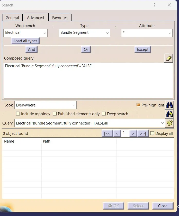
For flattening, flattening product is made and
geometrical bundle is flattened as shown below:
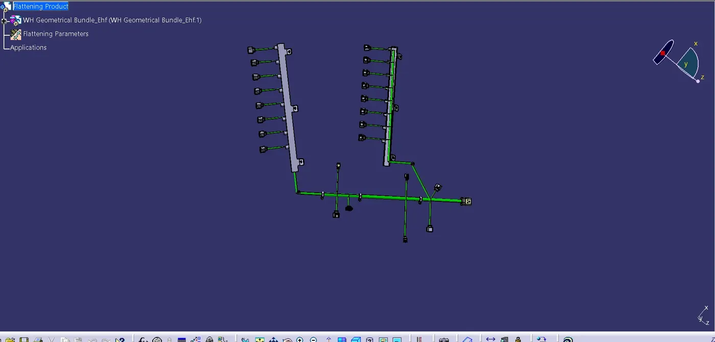
Since the routing is complex, we can't
simulate the actual shape into flattened structure. The drawing file of
flattened product is also created as shown below:
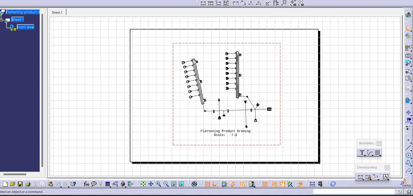
Critical checks like clearance of the bundle,
fouling of bundle with edges, bundle continuity, minimum bundle length,.... etc
are checked and is found OK. Application of all Packaging rules, Industry
best practices studied have been used in the design.
The below given google drive link contains all the zip files of the projects: