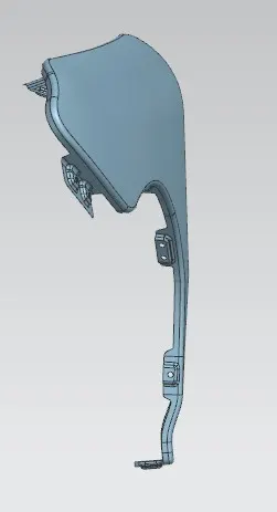
Fender Design
FENDER DESIGN
Fender is the part of an automobile, motorcycle or other vehicle body that frames a wheel well and prevents sand, mud, rocks, liquids, and other road spray from being thrown into the air by the rotating tire.
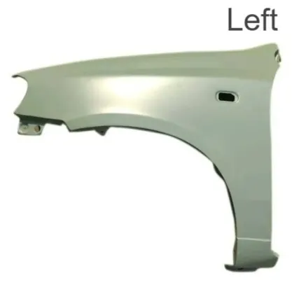
There are two types of fenders: full bumper type and half bumper type. Full bumper type fenders are made from a single block of metal and cover the entire wheel. Half bumper type fenders are made from two or three blocks of metal and cover only half of the wheel. Half bumper type fenders are more common and have less scrap and weight than full bumper type fenders. Fender on the left hand side of an automobile is shown in the figure below.
FENDER MOUNTS:-
Fender mounts are the points where the fender is attached to the vehicle body or other components. There are five major mounting points for a fender: drip area, A-pillar, sill, bumper, and cowl. The drip area is where the fender is fastened to the engine housing. The A-pillar is where the fender is fastened to the bottom edge of the windshield. The sill is where the fender is fastened to the lower part of the door. The bumper is where the fender is fastened to the front or rear end of the vehicle. The cowl is where the fender is fastened to the area near the windshield wipers.
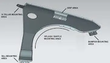
Fender mounts have different functions depending on their location and design. Some of their functions are: protecting the vehicle body from road debris and corrosion, providing structural support and rigidity to the fender, enhancing the aerodynamics and aesthetics of the vehicle, allowing for easy installation and removal of the fender, and accommodating various accessories such as lights, mirrors, antennas, etc .
Fender mounts can be classified into different types based on their shape, size, material, and attachment method. Some of the common types are: bolt-on mounts, weld-on mounts, clip-on mounts, adhesive mounts, and magnetic mounts . Bolt-on mounts are secured with bolts or screws and can be easily adjusted or replaced. Weld-on mounts are permanently attached with welding and provide high strength and durability. Clip-on mounts are snapped onto the fender or the body and can be quickly installed or removed. Adhesive mounts are glued onto the surface and offer a smooth and seamless appearance. Magnetic mounts are attached with magnets and can be easily moved or repositioned.
FENDER MANUFACTURING PROCESS:-
Fender manufacturing process involves three main operations: embossing, bending, and cutting and blanking. Embossing is the process of creating raised or sunken designs on the metal sheet using matched male and female roller dies. Bending is the process of deforming the metal sheet by applying force to create angles and curves. Cutting and blanking is the process of separating the metal sheet into desired shapes using punches and dies.
Fender manufacturing process can be classified into different types based on the material, method, and equipment used. Some of the common types are: cold stamping, hot stamping, plastic injection molding, composite molding, etc . Cold stamping is the process of forming metal sheets at room temperature using a stamping press and a die. Hot stamping is the process of forming metal sheets at high temperature using a hot stamping press and a die. Plastic injection molding is the process of forming plastic parts by injecting molten plastic into a mold cavity. Composite molding is the process of forming composite parts by applying heat and pressure to a mixture of fibers and resin in a mold.
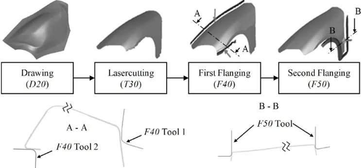
Fender manufacturing process has to consider various factors such as design, material, quality, cost, and environmental impact. Some of these factors are: part geometry, material type and grade, wall thickness, bend radius, emboss depth and width, flange width, fillet radius, dart size and location, parting line location, surface finish, dimensional accuracy, mechanical properties, corrosion resistance, weight reduction, scrap reduction, energy consumption, emissions reduction, etc . These factors have to be optimized to ensure that the fender meets the requirements of safety, aesthetics, aerodynamics, durability, manufacturability, and cost-effectiveness.
FENDER DESIGN PARAMETERS:-
Fender design parameters are the factors that affect the shape, size, strength, and functionality of the fender. Some of these parameters are: wheel arch clearance, parting line location, flange width, fillet radius, dart size and location, emboss depth and width, bend radius, wall thickness, material type and grade, etc . These parameters have to be considered carefully to ensure that the fender meets the requirements of safety, aesthetics, aerodynamics, durability, manufacturability, and cost-effectiveness .
- Wheel arch clearance is the distance between the outer edge of the tire and the inner edge of the fender. It is important to maintain sufficient clearance to avoid contact between the tire and the fender during suspension movement, steering angle, and tire deformation. The minimum wheel arch clearance depends on the vehicle type, suspension type, tire size, and wheel offset .
- Parting line location is the position where the fender is separated from the metal sheet during cutting and blanking operation. It is important to choose an optimal parting line location to minimize scrap material, avoid sharp edges and corners, and facilitate assembly and fastening. The parting line location should also follow the natural curvature of the fender and avoid interfering with other features such as embosses, darts, and flanges .
- Flange width is the distance between the outer edge of the fender and the inner edge of the flange. Flange is a flat or bent portion of metal that extends from the main body of the fender. It is used to attach the fender to other components such as drip area, A-pillar, sill, bumper, and cowl. Flange width should be sufficient to provide enough contact area for fastening and sealing. Flange width should also be consistent along the fender to avoid stress concentration and deformation .
- Fillet radius is the radius of curvature at the corner or edge of the fender. It is used to smooth out sharp transitions and reduce stress concentration. Fillet radius should be as large as possible without compromising the design intent and functionality of the fender. Fillet radius should also be consistent along the fender to avoid irregularities and discontinuities .
- Dart size and location are the dimensions and position of a triangular cut-out in the metal sheet that is used to facilitate bending operation. Darts are used to reduce wrinkling and tearing of the metal sheet during bending. Dart size and location should be optimized to achieve a smooth bend without excess material or gaps. Dart size and location should also be symmetrical along the fender to avoid asymmetrical bending forces .
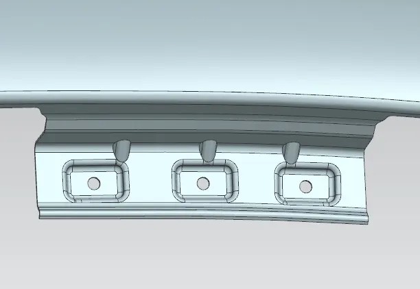
- Emboss depth and width are the depth and width of a raised or sunken design on the metal sheet that is created by embossing operation. Embosses are used to increase strength, stiffness, and rigidity of the fender. They can also enhance aesthetics and aerodynamics of the fender by creating patterns or shapes. Emboss depth and width should be proportional to the wall thickness and bend radius of the fender. Emboss depth and width should also be consistent along the fender to avoid irregularities and discontinuities .
- Bend radius is the radius of curvature at which the metal sheet is bent during bending operation. Bend radius affects the stress distribution, deformation behavior, springback effect, and fatigue life of the fender. Bend radius should be as large as possible without compromising the design intent and functionality of the fender. Bend radius should also be consistent along the fender to avoid irregularities and discontinuities .
- Wall thickness is the thickness of the metal sheet that is used to make the fender. Wall thickness affects the strength, stiffness, weight, durability, manufacturability, and cost of the fender. Wall thickness should be as thin as possible without compromising safety and quality standards. Wall thickness should also be uniform along the fender to avoid variations in mechanical properties .
- Material type and grade are the type and grade of metal that is used to make the fender. Material type and grade affect the mechanical properties, corrosion resistance, formability, weldability, and cost of the fender. Material type and grade should be selected based on the performance requirements, environmental conditions, manufacturing process, and budget of the fender.
FENDER DESIGN USING NX CAD:-
For the fender design, fender surface is provided. Our aim is to construct various mounting points by following the master sections provided which are of industrial standards. The drip area, A pller mounting area, baffles mounting area etc are created on the surface provided. Isometric view of the fender is given below:
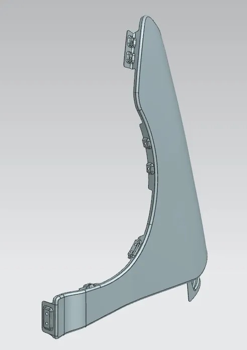
Different mounting points are designed as shown beow:
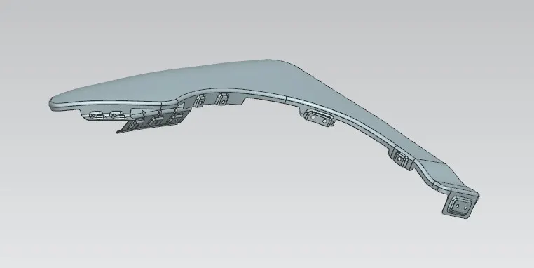
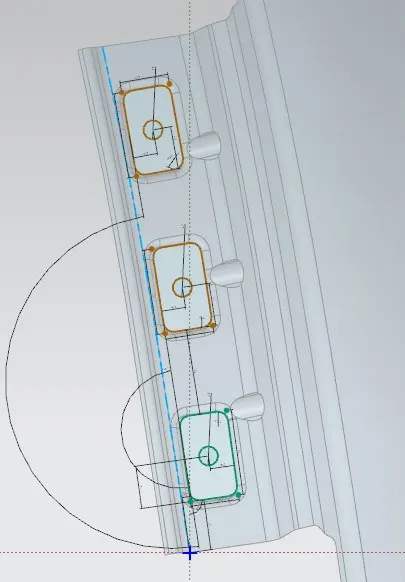
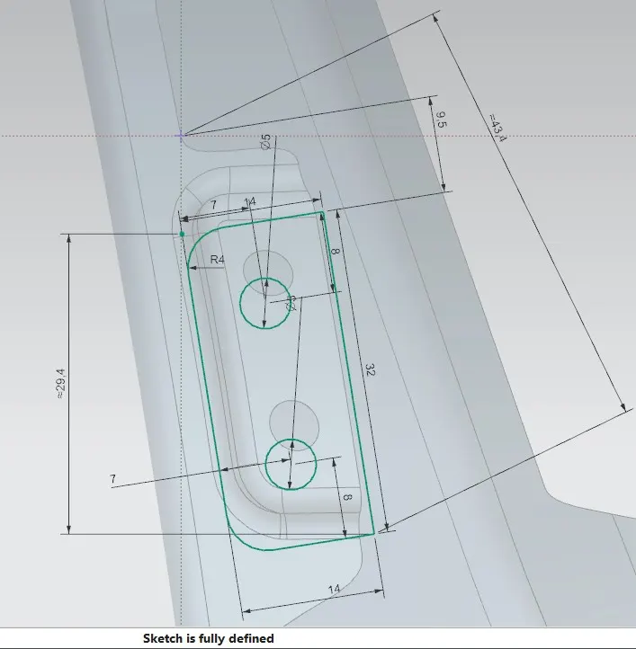
To remove sharp corners, edge filets as well trimming the sheet with appropriate curves were used. The different views of the final product is as shown below:
Front View:-
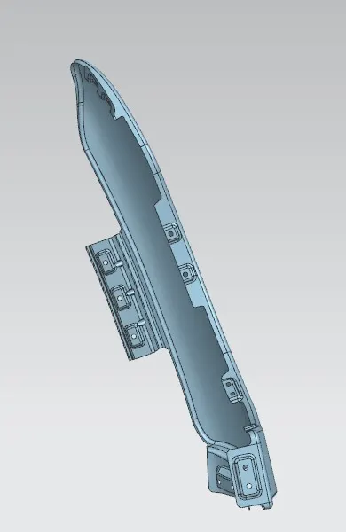
side view:
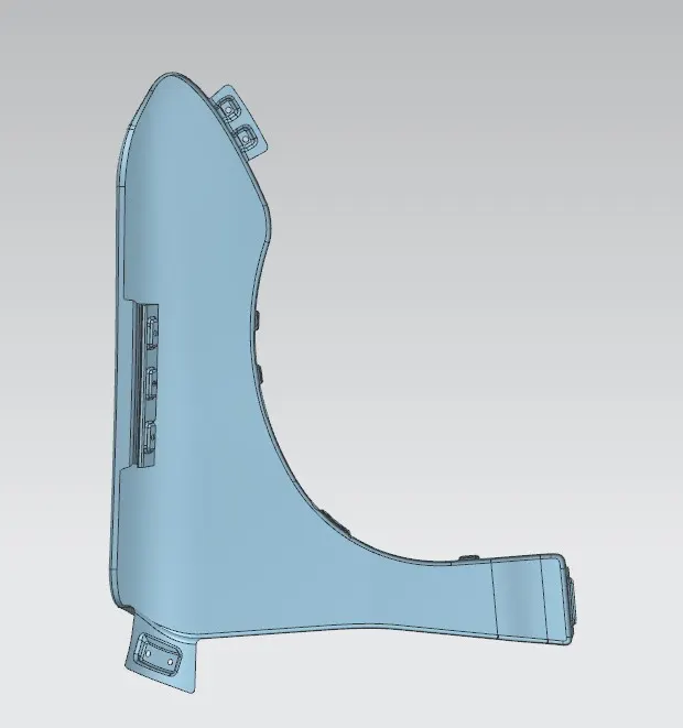
Top view: