Week 10 - Challenge 2- Attachment Feature Creation (Dog House)
DIFFERENT VIEW OF SOLID PART
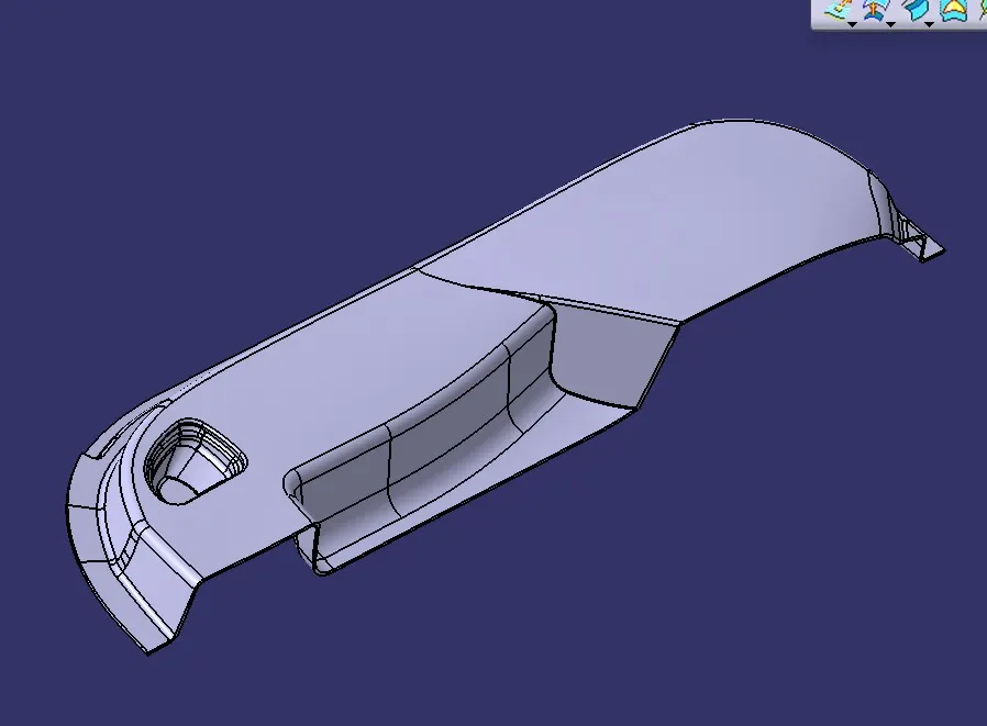
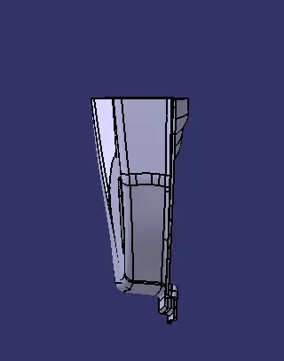
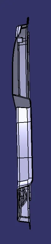
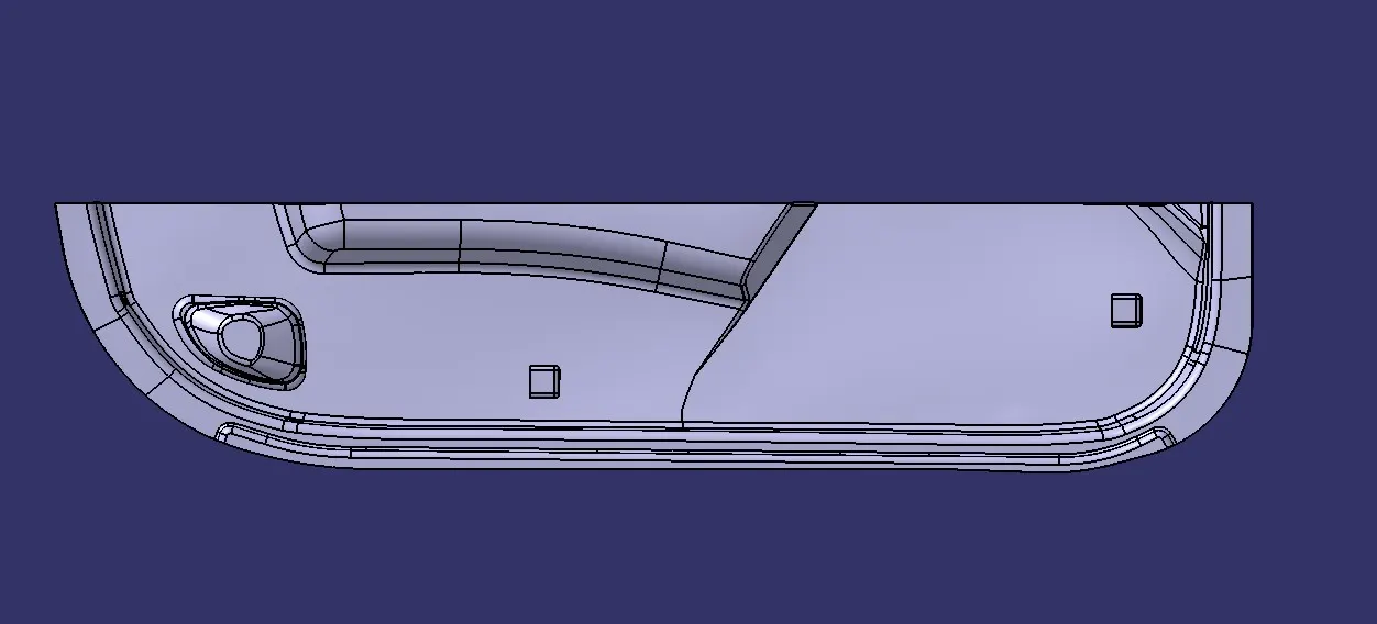
TREE STRUCTURE
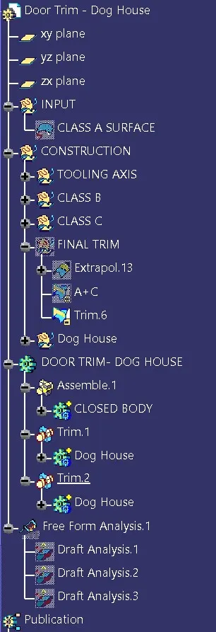
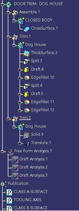
REPORT:
Door Trim
The door trim class A surface was provided for dog house design. Before starting modeling the solid plastic model, first thing to ensure is that the surface is free of defects/ flaws. Then the draft analysis is to be carried out.
Draft Analysis:
For draft analysi, a tooling direction is to be defined. Clearly the surface can clear the draft analysis with a normal axis. For that a small flat surface at the speaker set holder is extracted and a point is made on it. A line passing through this point in the Y direction (normal direction to surface) is created, which will serve as our tooling direction. Now draft analysis is done for the surface and the result is as follows:
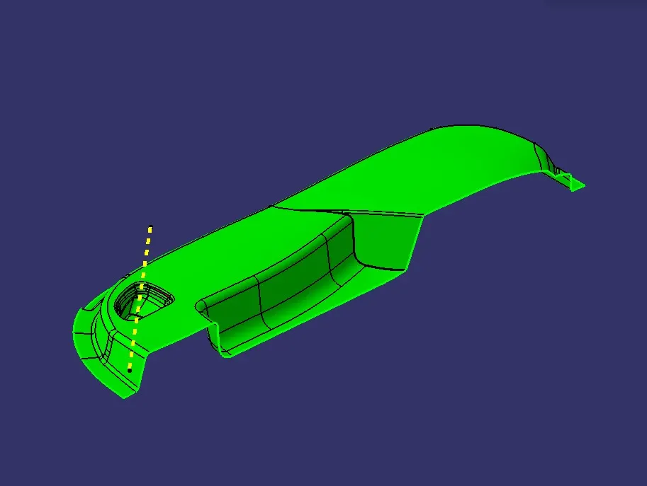
Though it looks like every corner is clearing the draft analysis, it is not actually. This is the problem with class A surface whch is to be cleared by engineers who developed class A.
NB: The 3 degree draft which is a mandate, is not cleared by every point.
Class B creation
Class B surface can be created by offsetting class A to a value of 2.5mm inside. This method will create some surface patch problems which is to be cleared using surface fill, multi section..etc
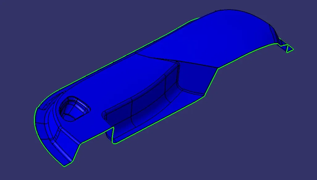
Surface in BLUE colour is class A and the yellow one is class B.
Class C Surface Creation:
Class C surface is the surface which connects class A and class B and forms a closed surface body. For the creation of class C, class A is used. The edges of class A are extracted and are swept with reference to class A at 90 degree to it. This typical model have some sudden bends and turns, which may not be captured using sweep. This type of problems may be eliminated using the proper use of multisection, surface fill...etc.
Solid body Creation:-
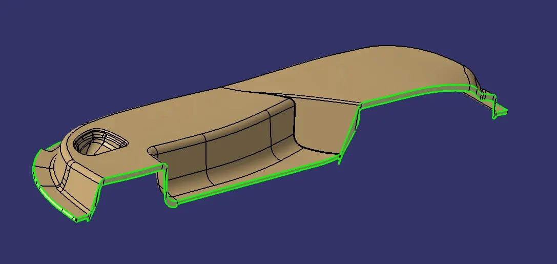
image of class A surface with class C surface is shown above:
For creating a solid body, the first and formost thing is we shoud have a closed surface. We join class A, B and C surfaces inorder to create this closed surface. First class A and C is to be joined using join tool. Sometimes this will not work, there we have to extrapolate class A and C by small length, say 1mm; so that they could be trimmed and avoid any chances of formation of open contours.
Then this assembly of class A and C is trimmed with class B to obtain final surface body. Then, in the part workbench, using closed surface feature, solid body is created. (ABO)
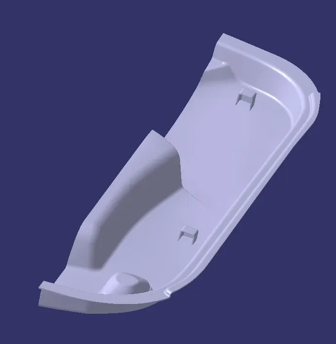
This is the final output- the solid body.
After the creation of the solid body, we have perform the draft analysis.
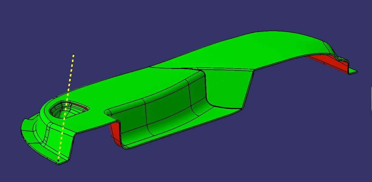
The draft analysis of solid bod seems okay with minor variations.
Dog House Creation:-
The surface on which dog house is to be created is extracted and a point is created on it. A plane tangent to the XZ plane is made through this point in order to get a base. Sketch for dog house is created here.Figure shows the sketch for dog house. This sketch is extruded to form a surface, with reference to draft direction. The base surface is again offsetted to form the basic frame of dog house. Again other features such as fillets, the inner cut to avoid sink marks etc are created to form the dog house. the draft analysis of dog house with main tooling axis. Draft angle required is 1.5 degree fr outer surface which is satisfactorily cleared.For the inner part, we gave a draft angle of 0.5 degree, which is cleared with side core axis's draft analysis.
T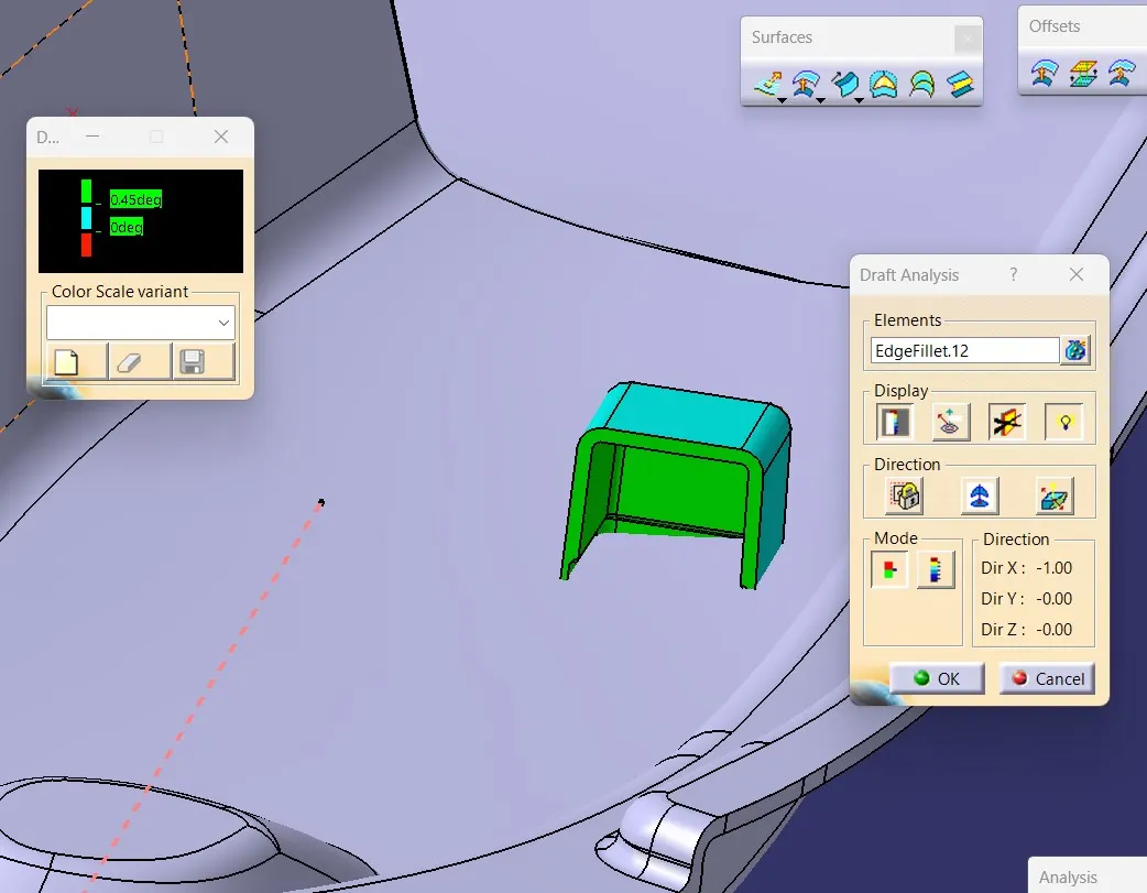
Hence the model has been created with prescribed engineering feature and design considerations.