Wiring harness routing & packaging Rules Week 3 Challenge
P-Clamp
P-clamp is a clamp used to define the wire routing. They are fasteners used to ensure support and retention to cables/wires when fastened to chosen application.
For electrically defining a P-Clamp the following steps are done:
1) Get the 3D part
The 3D part is downloaded using the link. The Clamp has a plastic part around which a ruber part is placed.
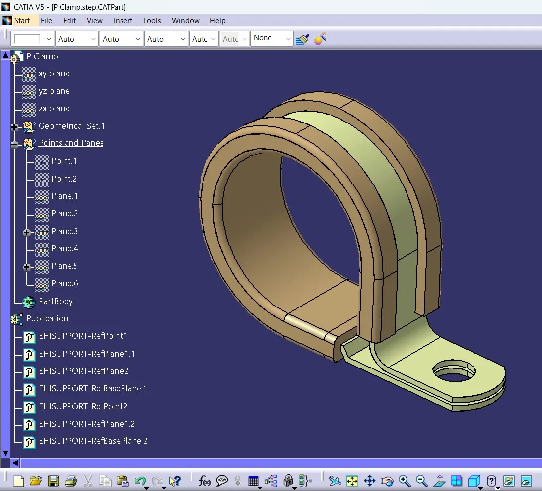
2) Define the geometry parameters
The entry point, entry plane, exit point, exit plane and base plane is created using the mechanical part design.
3) Define part as support
The P - Clamp is defined as a support in electrical part design. Here there are two entry points, so we have to define this two times.
4) Define entry point and plane
5) Define base and exit plane
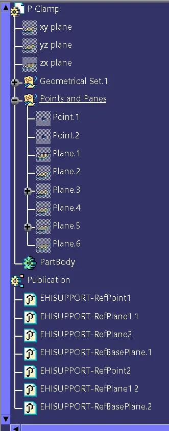
These are the publications generated automatically as the result of defining the clamp as support two times.
Catalogue Creation:-
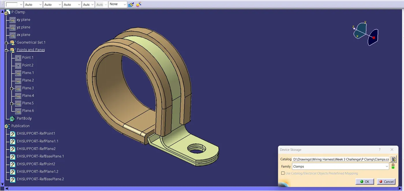
A catalogue is created for clamps and P Clamp is added to it.
BACKSHELL
Backshells are plastic molded parts used at wire entry side of connectors either for protection or to improve aesthetics/appearance of harness. They are not mandatory parts of wiring harness, are always optional and driven by cost.
The following steps are involved in electrically defining a backshell:
1) Get the Backshell 3D part
The 3D part is downloaded using the link provided.
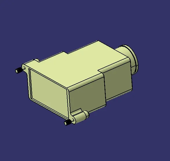
2) Define the geometry parameters
Backshell Connection point as well as backshell connection axis is created on the mating face of the backshell. Also Bundle connection point is created on the bundle connection face.
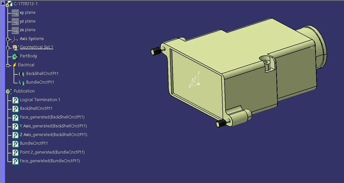
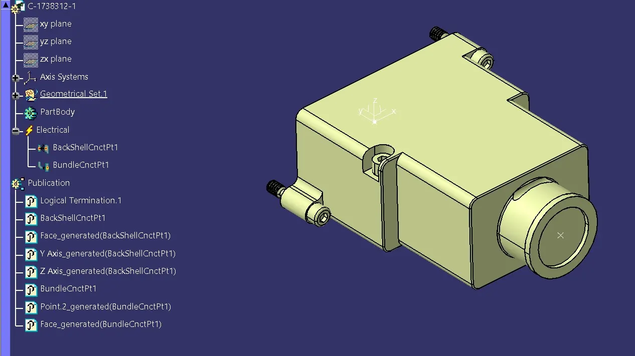
3) Define the part as backshell
The backshell is electrically defined in electrical part design workbench.
4) Define Backshell Connection Point
The backshell connection point s defined using previously created point and axis.
5) Define bundle connection point
The bundle connection point for backshell is also created using previously created point.
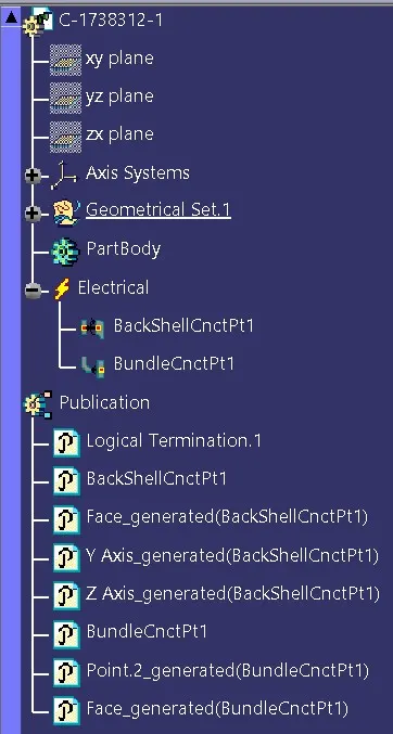
The tree status after electrically defining the part.
A catalogue is created for backshell and the part is added into it.

CORRUGATED TUBES
They are used to protect the wiring harness. Following steps are used for electrically defining corrugated tubes:
1) Create covering 3D part.
2) Create catalogue for Coverings
3) Add new part in Catalogue
4) Apply covering on harness bundles from catalogue
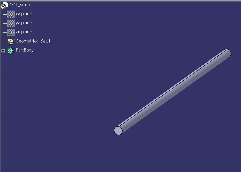
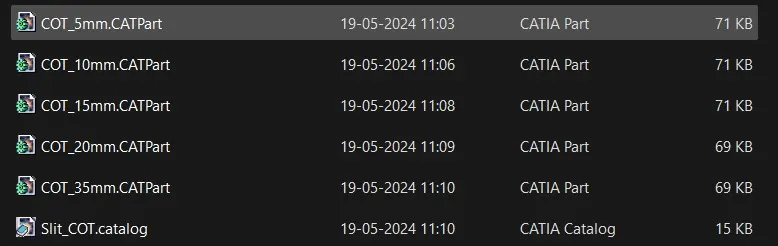
A catalogue named Slit COT is created for corrugated tubes as follows:
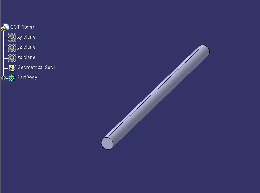
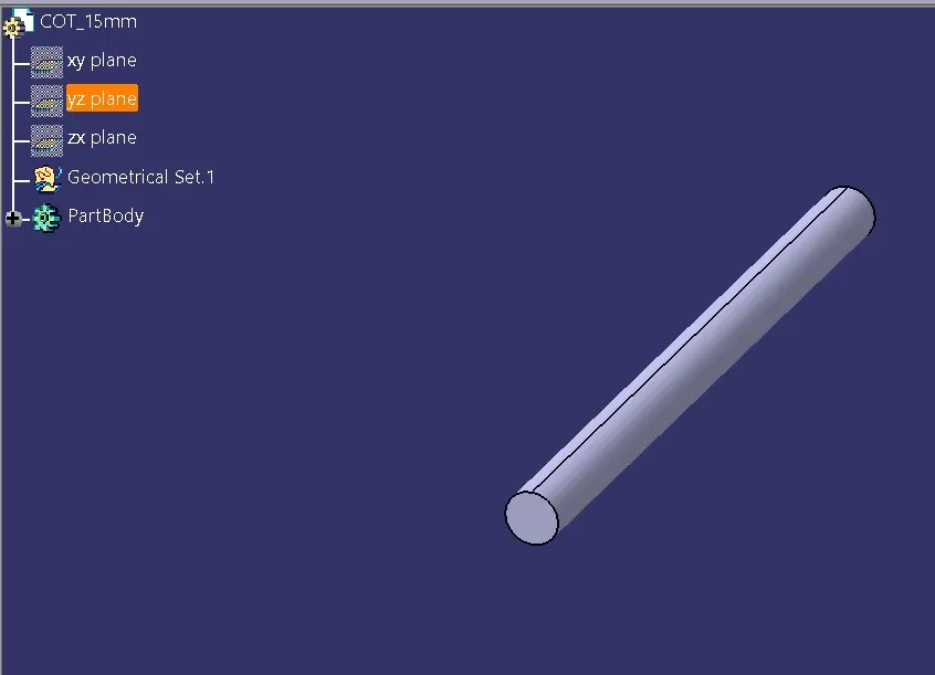
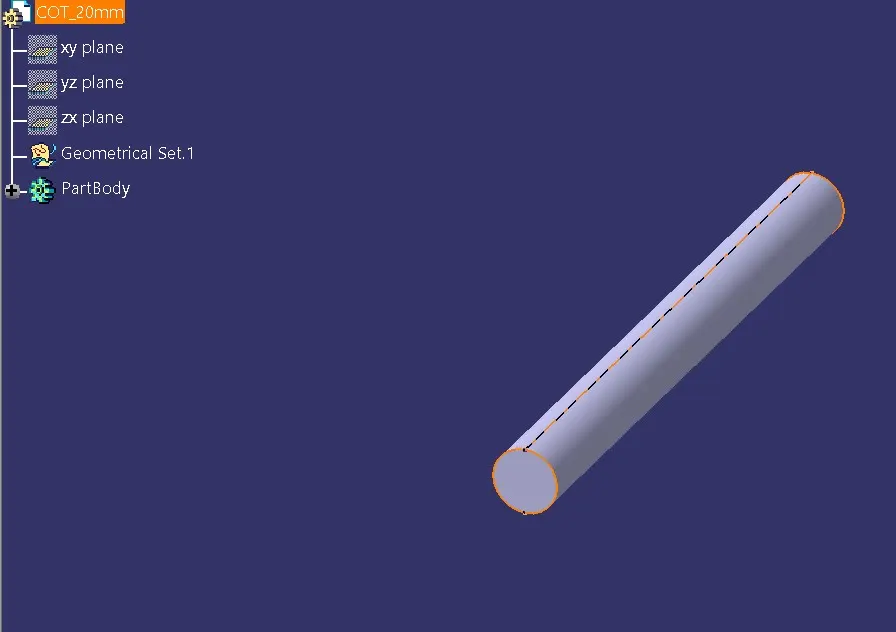
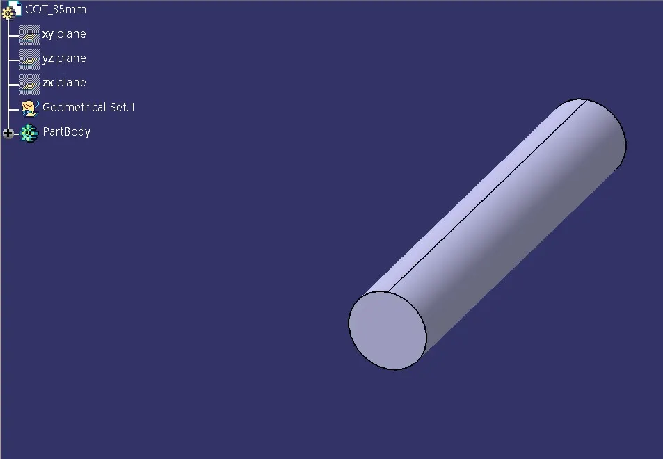
Please note: All supporting files
are attached below.