Week 11 - Project - A pillar Design with Master Section
PILLAR DESIGN WITH MASTER SECTION
Class A surface of pillar along with master section was given for creating a solid body out of it. Going into design first thing to ensure is that the given surface is free of surface irregularities and flaws. After checking, draft analysis of class A is to be done. For that tooling axis needs to be created.
Tooling Axis creation:
Tooling axis is created using an arbitrary point on the surface and a line is drawn through this point in the normal direction to the surface. This line will act as our tooling axis. Now draft analysis is to be carried out.
Draft Analysis of Class A:
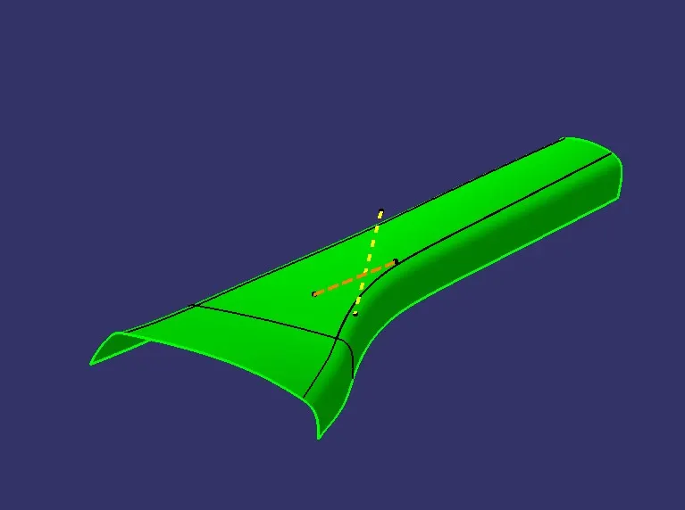
Draft Analysis of class A is satisfactory with 3 degree draft angle along tooling axis. Now we can move on to further modeling.
Class B Surface Creation:
The class B surface is created with the use of class A. 'A' Surface is offsetted to 2.5mm inside. Some patch corrections are to be made because offsetting fillets will cause problems to the offsetted surface.
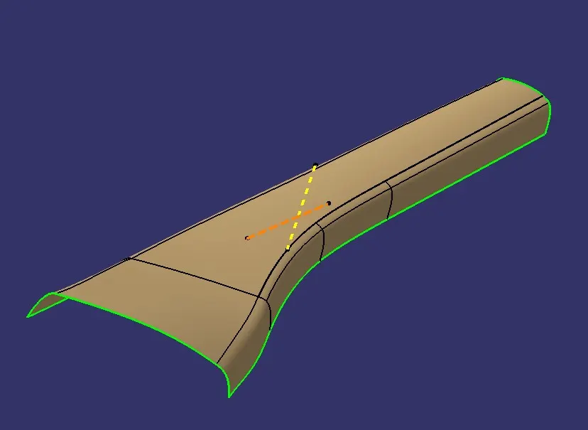
Figure shows the class B surface
Class C Surface Creation:
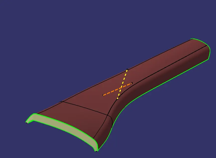
Class C surface is the surface which connects class A and B together. It is created using class A surface. The boundaries of class A are swept at 90 degrees with reference to class A. This can also be created with respect to draft direction.
Closed Surface Creation:
Once the three surfaces are created, they can be trimmed and joined together to get a closed surface body.
Draft analysis of Solid body:
The draft analysis of solid body is carried out with respect to tooling axis. The results are shown below.
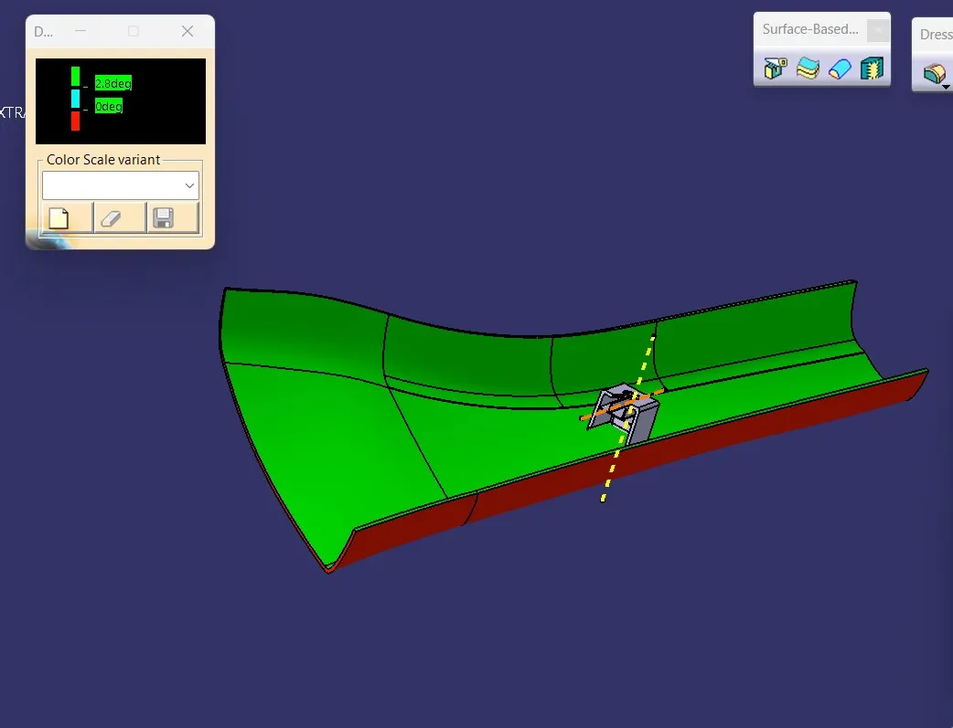
Though there is some problem with a small portion in the C surface area, the results are satisfactory with 3 degree draft angle. This occured due to some twist happened to C surface while sweeping.
One the draft analysis of the solid body is completed, we can move on to design of engineering features.
Dog House Design Using Master Sections:
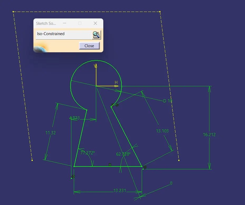
We are provided with master section of dog house. A reference drawing was also given, though it s not followed completely as some dimensions were found contradictory. In my design, dog house was made completely based on master sections given. First the outer most walls were made by extrating the lines from master section and extruding them to surfaces. Then they were thickened using thick surface coomand in part workbench.The bottom surface seems non-continuous, but it is irrelevant as the base going to be trimmed off with our main solid. After this base frame creation, the ribs and cross bar inside the dog ouse is created and trimmed to join with the base frame. Now for the top cut-out, a sketch is created whose sketch solving status is given below:
Draft analysis of dog house:
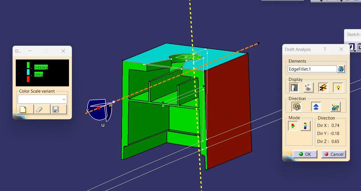
The draft analysis of dog house with tooling axis as well as side core axis is given above.The side core axis is made perpendicular to the tooling axis. The results observed are satisfactory.
Final Output:
After creation of all the engineering features, they are to be assembled with main body. Boolean operations such as add, assemble, union trim are used for this. Finally the draft analysis of the complete body is to be done with tooling axis and side core axis.
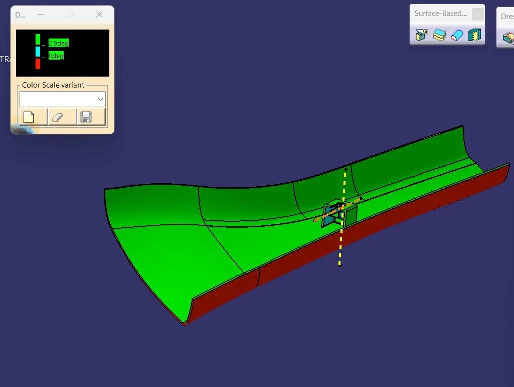
The figure shows draft analysis with respect to main tooling axis.