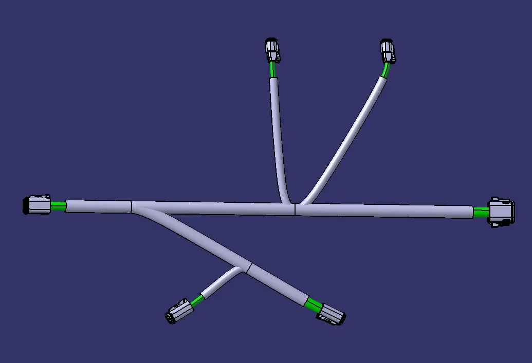
Wiring harness design in CATIA V5 - 3D modeling Week 4 Challenge
The objective of this challenge is to create a wiring harness routing as given in the layout. For that 4 different connectors are given namely:
- DT06-4S
- DT06-6S
- DT06-2S
- DT06-08SA
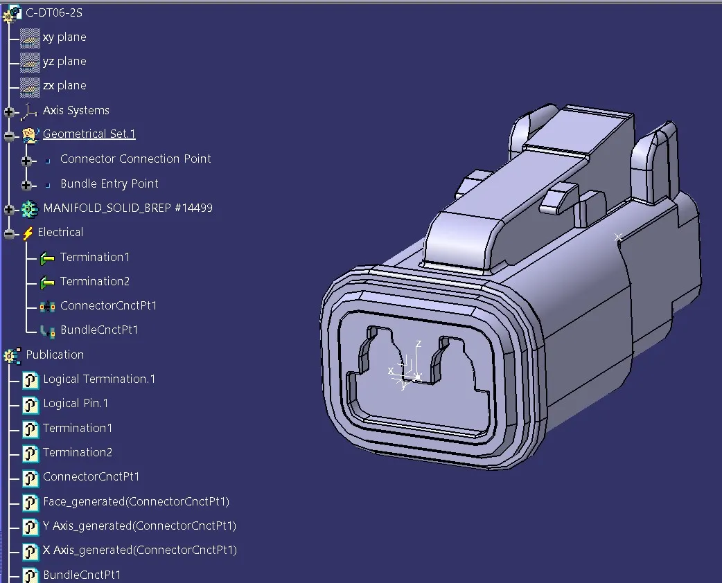
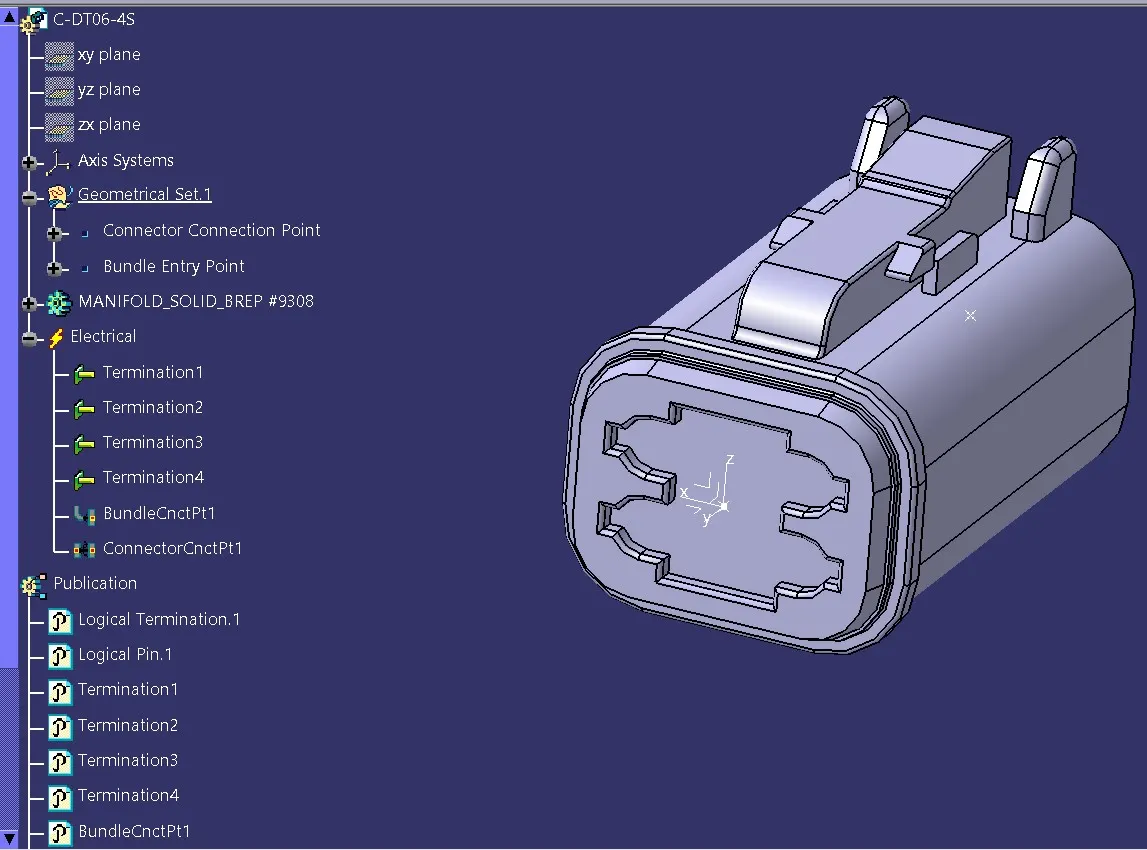
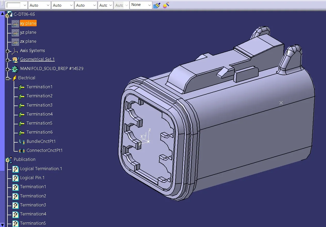
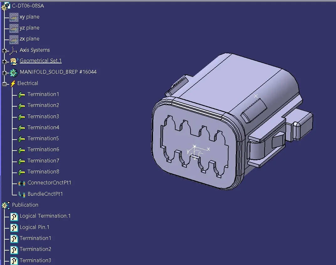
After electrically defining each component, they are stored into a catalogue named as Connectors.
Now we can proceed to Wiring Harness Assembly.
Every Harness context assembly file contains a Geometrical Bundle assembly file and an Electrical Bundle assembly file.
They are created in order as shown below:
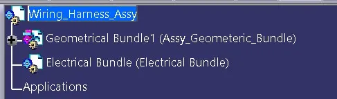
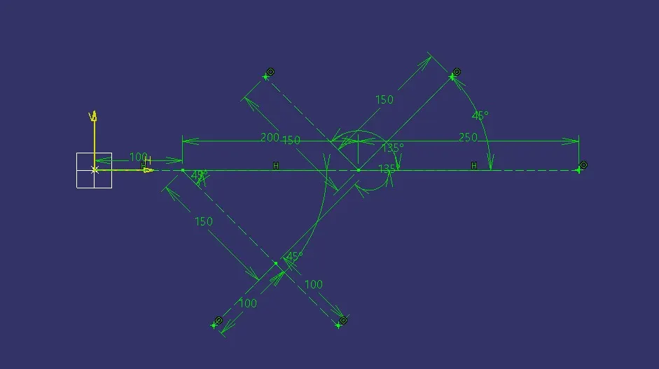
To place the connectors as per the given wiring
harness diagram, some reference is required, because we can't place it in free
space. So a sketch in which points are created as per the given diagram, where
each point represents the position of each connector. This is done only for the
ease of placing the connectors as per the diagram. The sketch and the created
points are as in the figures below:
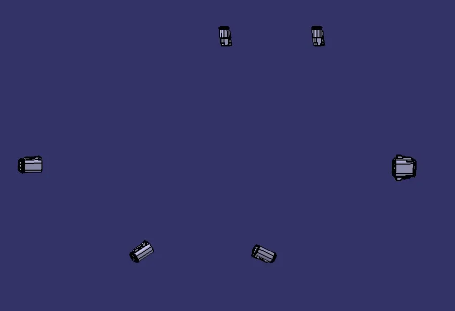
Now, using these points, the connectors are
put in place, and rotated using rotate command to be in proper direction as
shown below:
With this, our preliminary work is complete.
In the next phase, we enter into the electrical harness assembly. So we move to Electrical Harness Assembly Workbench. We should ensure that our Geometrical bundle is electrically defined.
First a multi-branchable document is created using the icon. First branch is created between DT06-08SA and DT06-06 connectors, of 10mm diameter. Then branch points are created on this main branch at 100mm, 300mm from DT06-08SA connector end as per the layout. Then branches are created to the other connectors as per the layout as shown in the figure below:
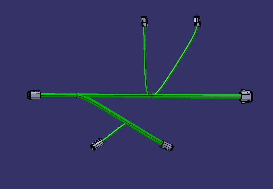
After the completion of creation of harness
bundle creation, protection coverings are added to each branch. The main branch
is given a 15mm tube covering where as the sub branches are given 10mm tube
covering. The end extremity in each connector side is made to 30mm as per the
guideline. The final output is as shown below: