Wiring harness design in CATIA V5 - 3D modeling Week 2 Challenge
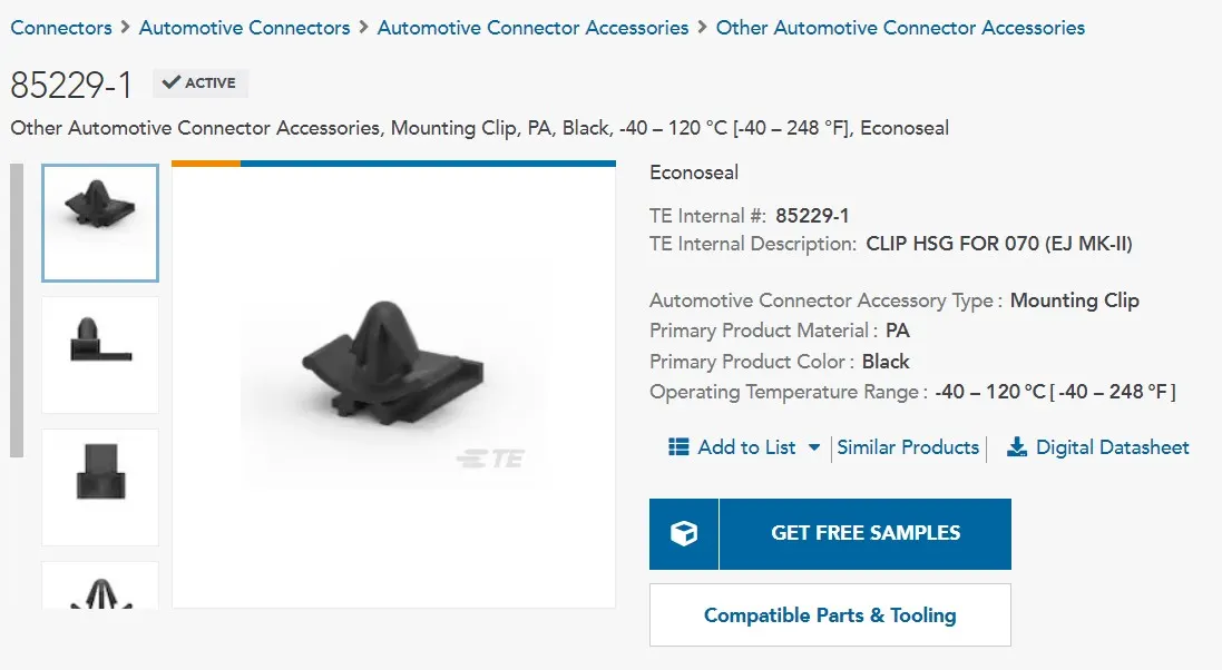
This is clip
The following steps are followed for electrical connector definition:
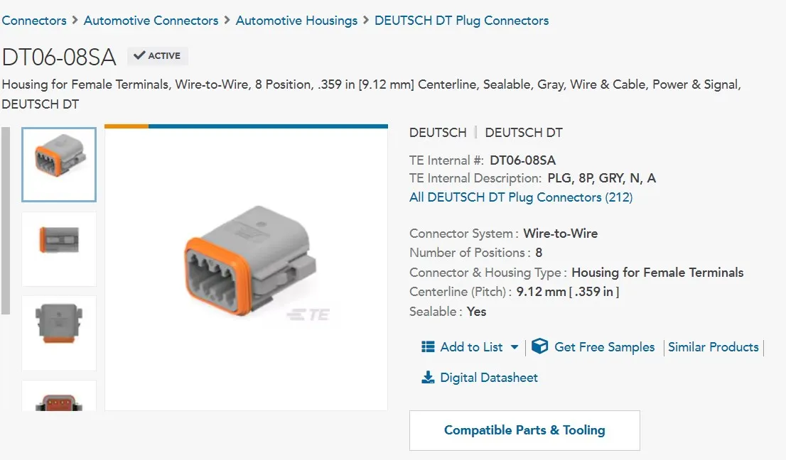
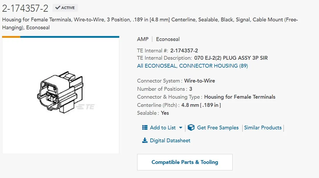
1) Download the connector 3D file
Using the given link, the 3D stp files are downloaded for the 3 parts. Then these are to be saved as CATIA Part files.
2) Creation of required geometrical paramenters
Once we have the 3D CAD file, Connector connection point with connector connection axis is to be created on the parts. For a female connector, connector connection point is the point where the male part gets mate with its connector connection point. This step is not applicable for connection clip.
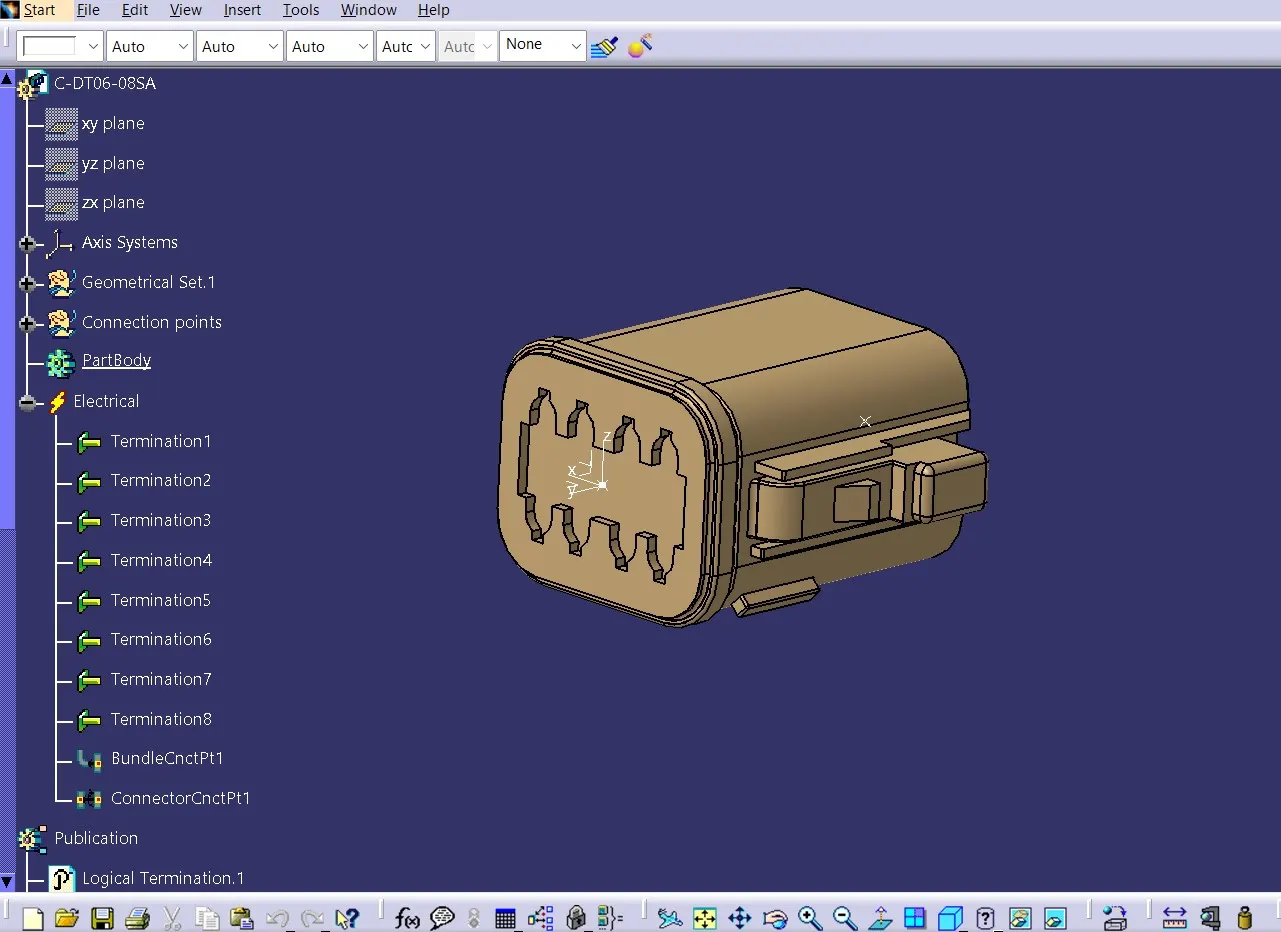
The following figure shows the connector connection point with axis created on DT06-08SA:
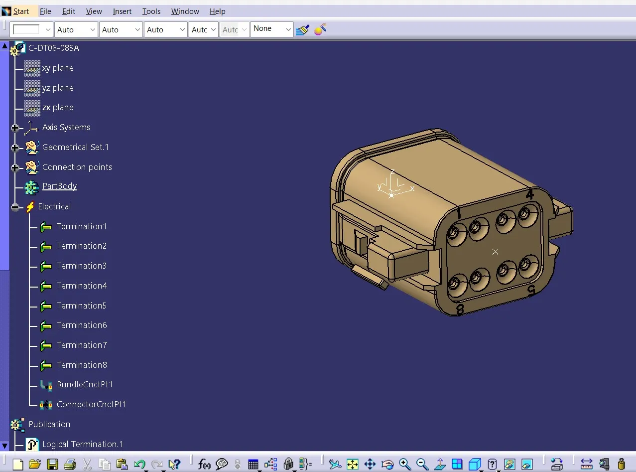
The figure below shows the bundle entry point for DT06-08SA:
This step is done for 2-174357-2 as well.
3) Define the part as connector
This is the first step where we define the parts as an electrical component. The point and axis creation are carried out in Mechanical part design where as for Connector definition step onwards, we are using electrical part design.
For the connector clip, it is to be defined as a mounting equipment.
4)Define Bundle connection point
Bundle conection point is to be defined in electrical part design workbench for each part (bot for connector clip) using the early created bundle connection point.
5) Define Connector Connection Point
Using the connector connection point and connector connection axis, the connector connection point is to be defined for both the connectors. This step is also not applicable for connection clip.
6) Define Cavity Connection Point
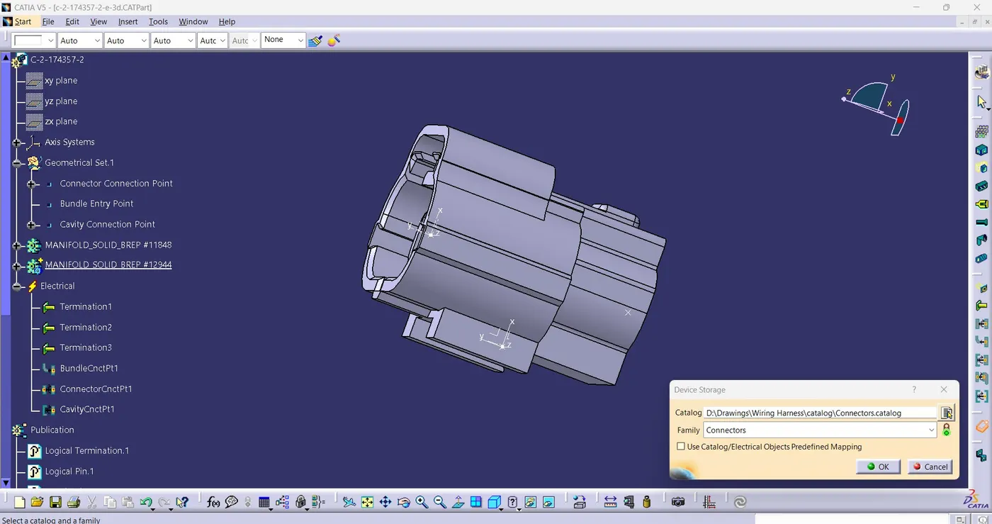
Cavity connection point is the point where a clip gets mates with the connector. 2-174357-2 is a connector having a provision for fixing a connector clip on it. So a cavity connection point and an associated axis is create on the mating face of the connector on which the clip gets mate. After creating the point, the cavity connection point is to be defined in the electrical part design workbench. For the clip, we define cavity. The corresponding images are given below:
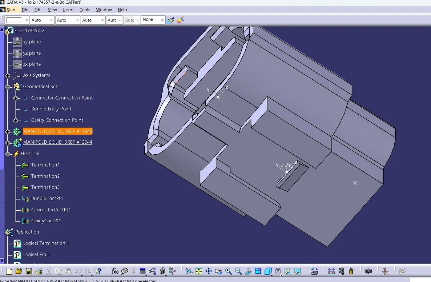
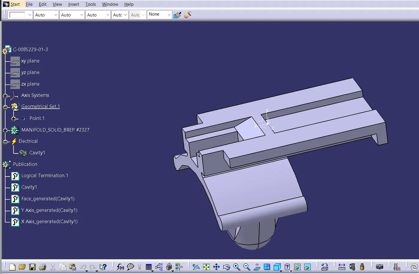
Care should be given that both the axis should be alike in orientation for mating.
After defining the electrical components, they are to be added to the catalogue created as shown below: