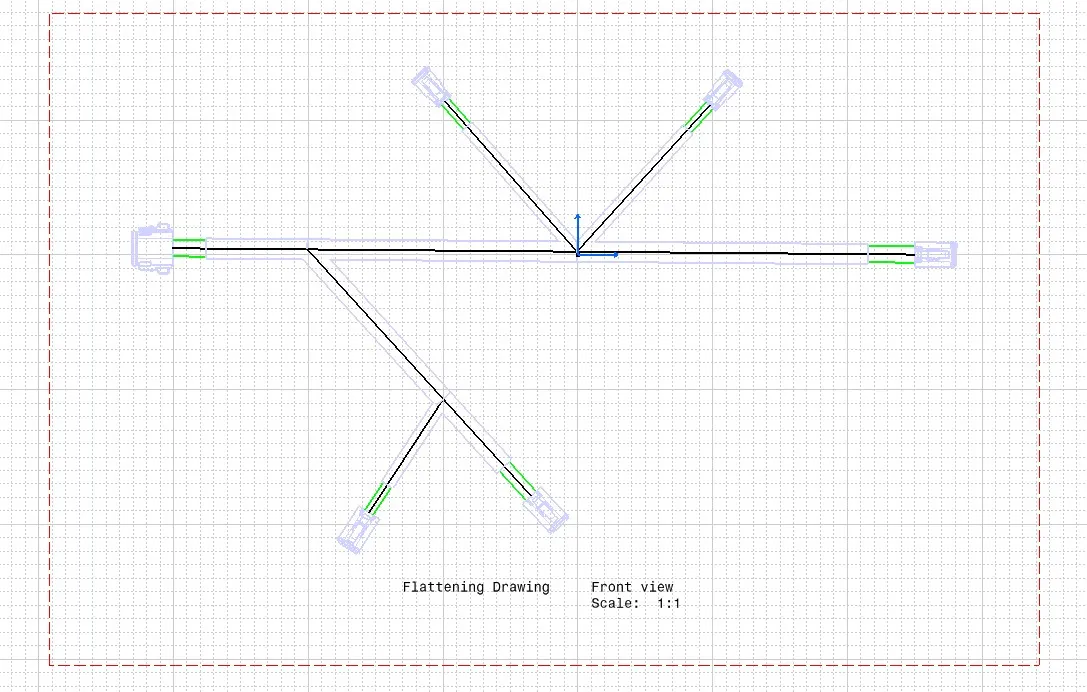
Wiring harness design in CATIA V5 - 3D modeling Week 7 Challenge
In the week 4 challenge, 6 connectors namely DT06-08SA, DT06-4S (2 nos.), DT06-2S (2 nos.) and DT06-6S were given and they have to be routed as per the layout given. So, the CAD files for the connectors were downloaded, electrically defined each connector and they were stored in the catalogue for connectors. After that, they were put up into an assembly of geometrical bundle and positioned as per the layout given. Then routing was done between the connectors as per the given specifications for routing. Further, cot-tubes were made and they were added into the geometrical bundle assembly.
The final output of the above said processes is shown below:
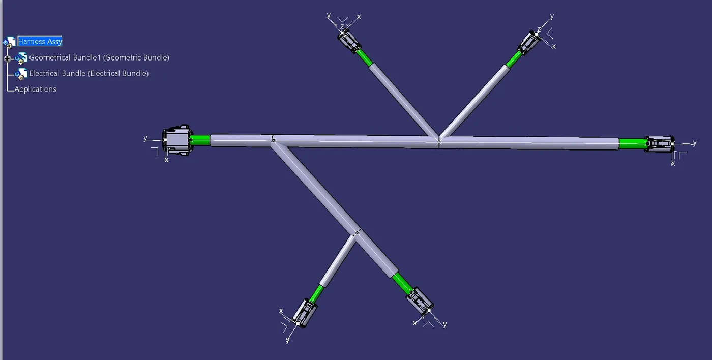
Now the geometrical bundle given above is the input for this challenge.
FLATTENING
For flattening, a new product named Flattening Product is created and is stored in the same file location of that of the geometrical bundle assembly. Then, both the geometrical bundle and flattening windows are tiled vertically for easy extraction as shown below:
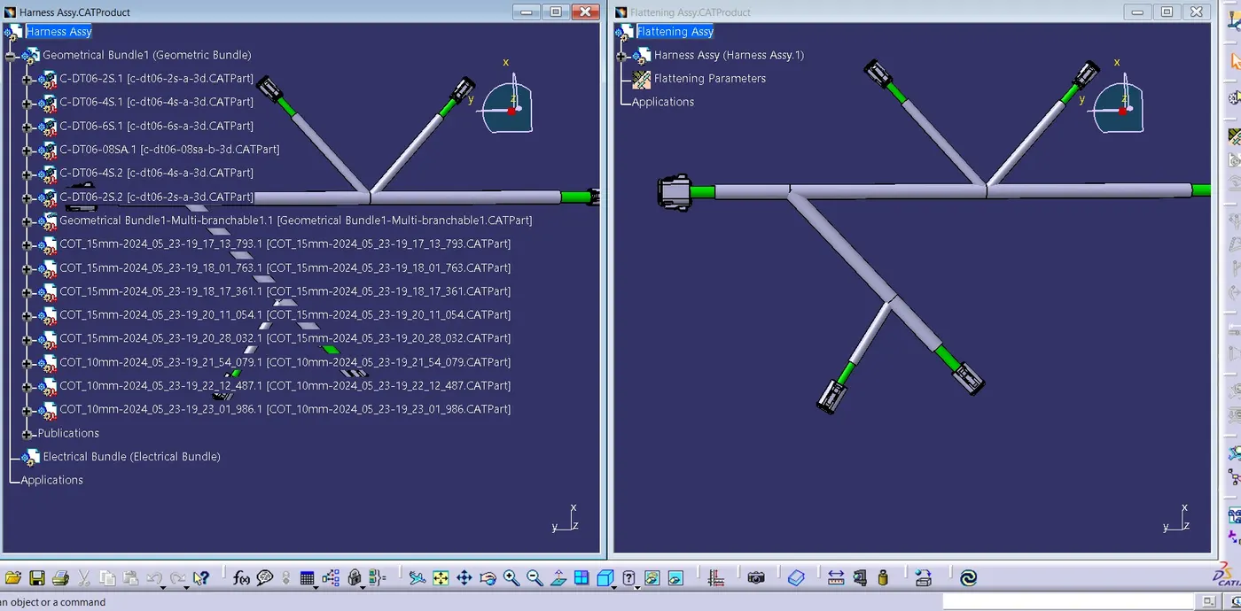
In the Electrical Harness
Flattening Workbench, using extract command, the geometrical bundle is
extracted on to the flattening product. On successful extraction, the name of
the geometrical bundle gets Ehf as suffix, which is verified and shown below:
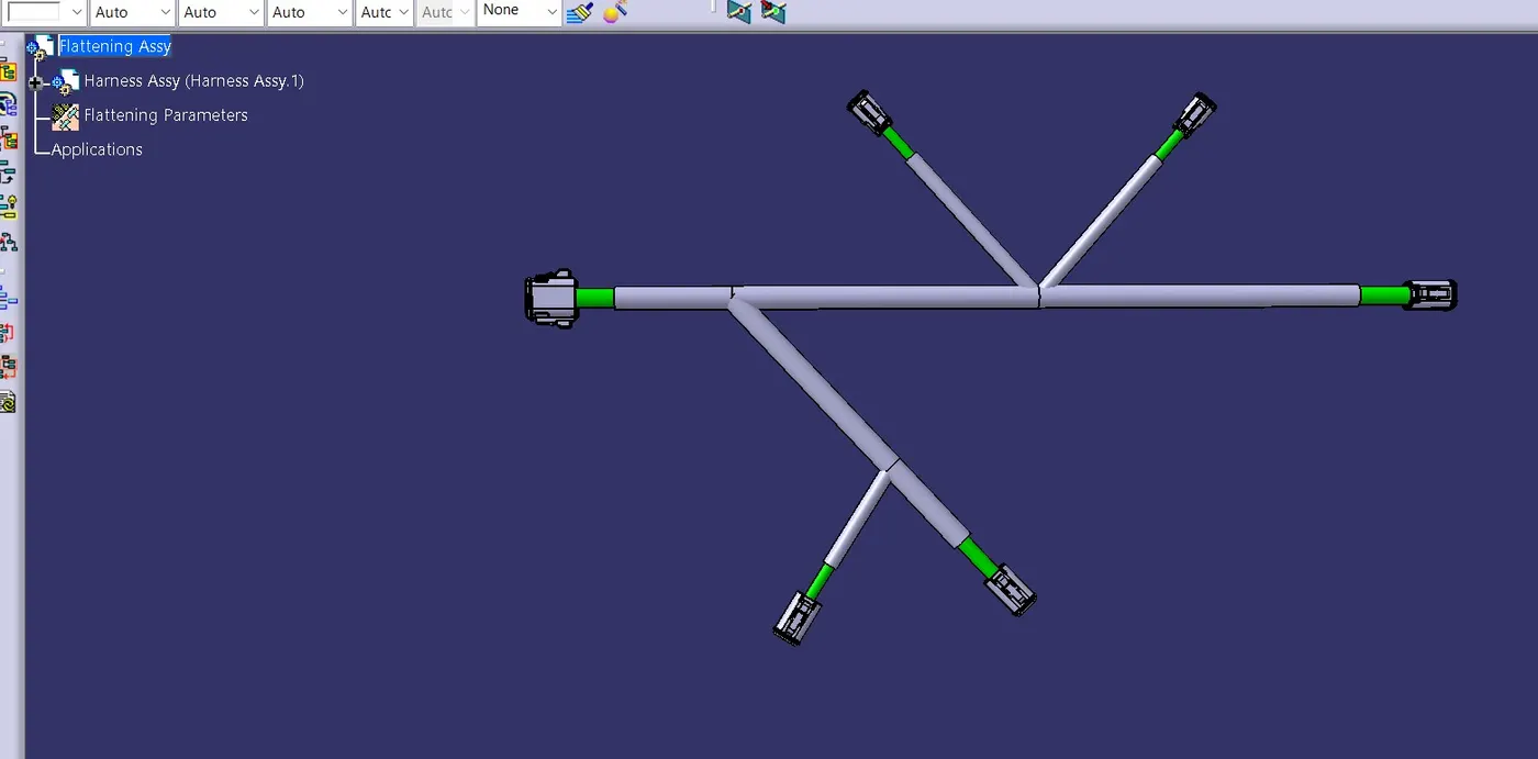
Using the flatten command, the assembly is made into a 2D plane. Now we need to position the connectors as per the layout given. Using the commands like rotate, roll, bend etc. we can fulfill this. Here I have used only rotate command, since it was only required:
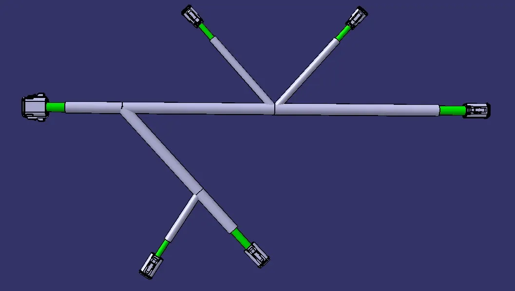
Our work in Electrical Harness
Flattening Workbench is completed. A new drawing file is created and the
flattened harness is exported into it. A0 size with ISO standard is used.
Proper color codes are given and line thickness of bundle segments are
adjusted for proper view. Brown and blue lines shows the Cot-Tubes, green lines
shows the harness bundles. The drawing is as shown below: