Week 9 - Challenge 1 - Base Bracket Design
BASE BRACKET:
Notations:
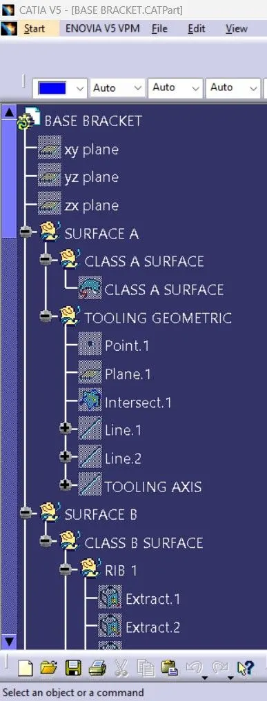
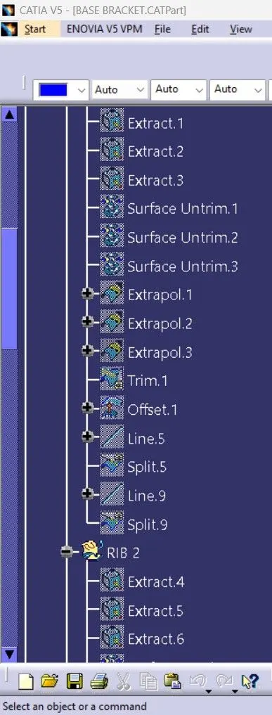
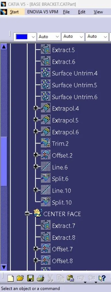
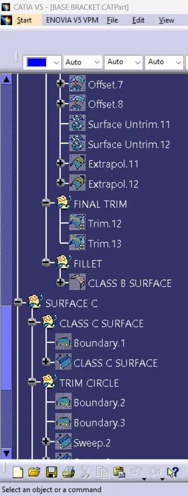
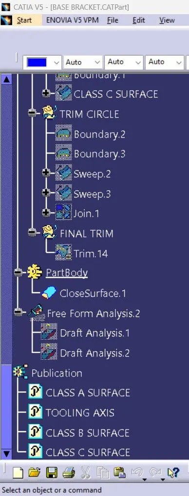
- Maintained proper tree stucture and gave proper name to geometric set.
- All sketches and surfaces have made under geometric set and close surface command is under part body.
- Also publicated tooling axis, class A, B and C surface.
Design steps:
- For making final close body from surface we need Class A surface for creating Class B and Class C surface.
- First need to create tooling axis for creating draft and for draft analysis with help of intersection command.
- Then need to extract and untrim the Class A surface's different surfaces to make Class B surface and need to give offset to that extract surface.
- Then one by one need to extract all surface and offset it and need to trim them for connecting them.(Offset of 2.5mm as per notation)
- That's how we create Class B surface and after then with the help of Class A surface boundry we can create Class C surface which can connect Class A and Class B surface.
- Then at the final step after connecting Class A,B and C surface with each other with the help of trim command need to apply close surface command to make it solid body.
Tooling axis steps:
- For making tooling Axis need to check where we can create partition line or intersection where we can easily pull out the body after moulding process.
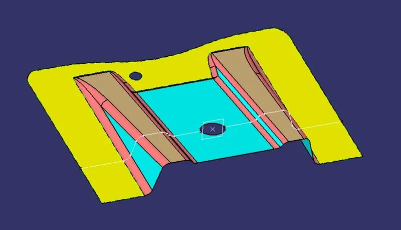
- Like below picture we can see i chose circle and make plan then use intersection command to create continue line on Class A surface.
- After this need to make line on taper surface/line to create bisecting line which we can understand below picture.
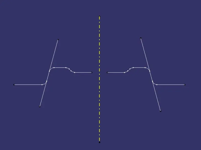
- With help of taper line we can create bisecting line which we can use for tooling axis and in upper picture center yellow line is tooling axis.
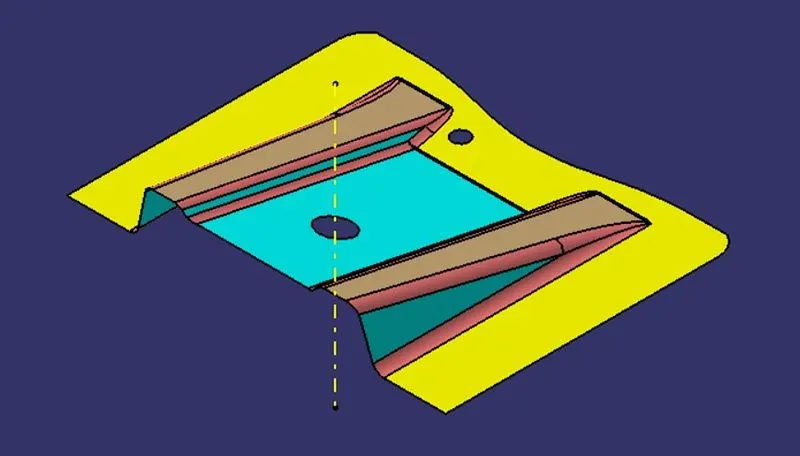
DRAFT ANALYSIS:
Class A surface draft analysis:
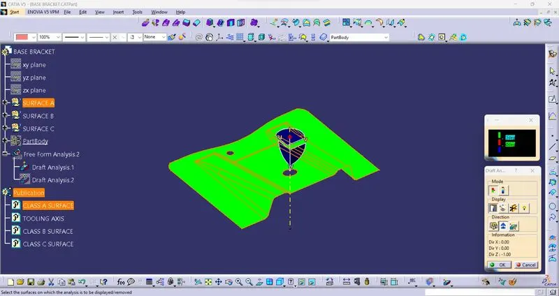
- Below picture we can see how draft analysis look like for Class A surface with help of 3° degree.
- Draft analysis is analysed by tooling axis for that need to use draft analysis command and for that need choose point on tooling axis and need to select whole Class A surface and then give 3° degree and like below we can see whole surface is green which means whole surface is having 3° or more than that which can easily pull out in moulding process.
Final body draft analysis:
- For final body draft analysis process is same as which used for Class A surface draft analysis and below picture we can understand how final body draft analysis look like.
- In below analysis which body side is having green colour, That is having 3° or more than that which is good and which having blue colour which means that is having between 0° to 3° which is okay but not good as green colour side. and if we having red colour then it's less than 0° which is not good means that is having wrong design which need to modify and will having problem for pulling out in moulding process.
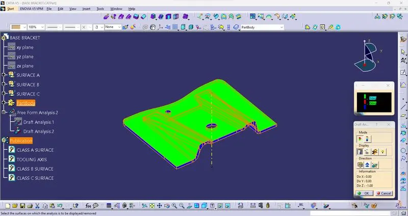
Class A surface:
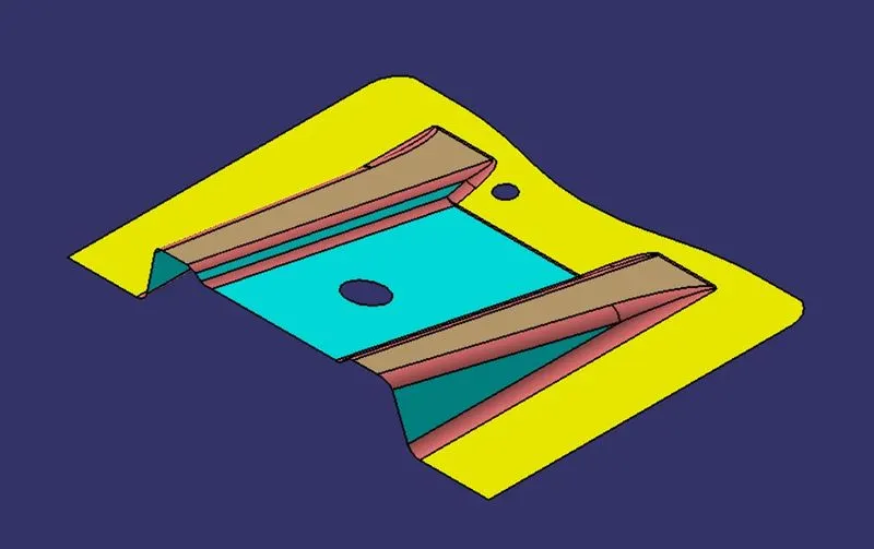
Class B surface:
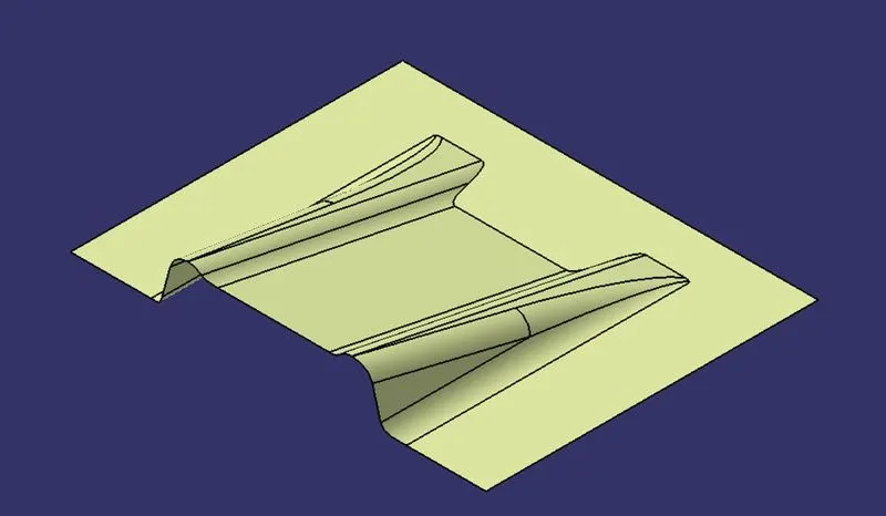
Class C surface:
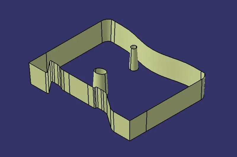
FEATURE COMMAND TREE:
DIFFERENT TYPES OF VIEWS:
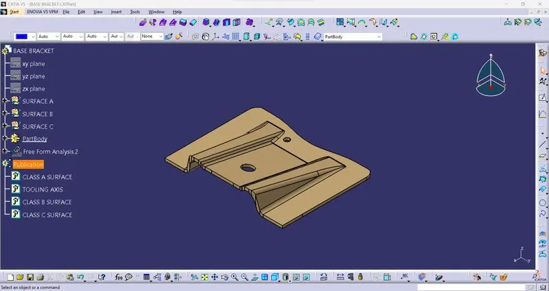
Isometric view:
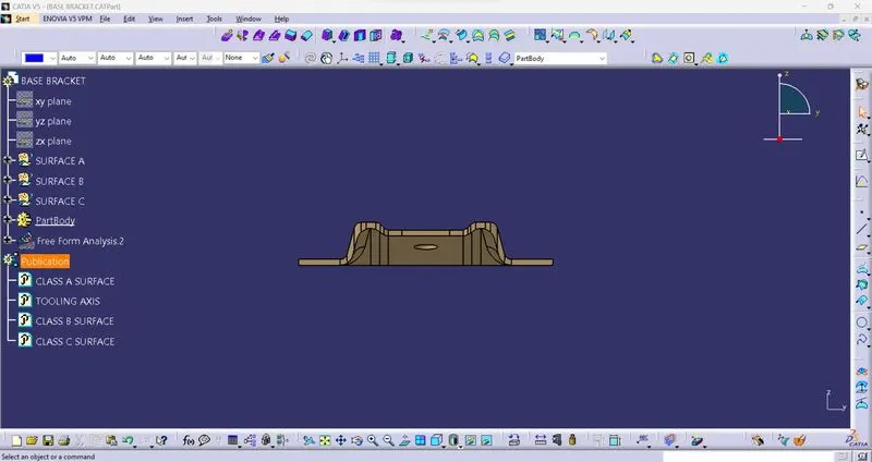
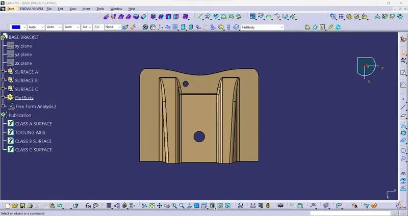
Front view:
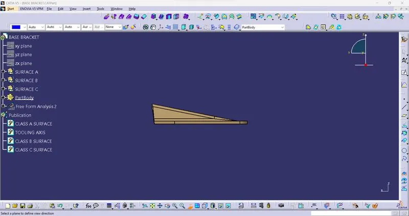
Side view:
Top view:
Conclusion: In this challenge i have leanred how to create Class B and Class C surface with the help of Class A surface and also leanred how analyse the draft with the help of tooling axis and draft analysis.