Wiring harness design in CATIA V5 - 3D modeling Week 2 Challenge
3D MODELING:
Steps:
- As per given link have downloaded cad model connector and mounting clip.
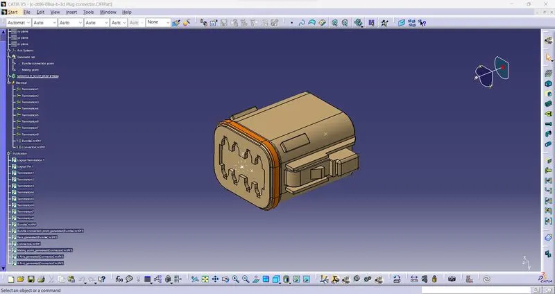
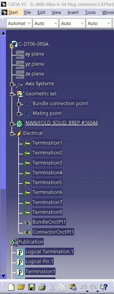
- For creating that cad model to electrical connector have used electrical part design and in electrical part deisgn have used define connector command also for convert mounting clip in electric part have used define mounting equipment.
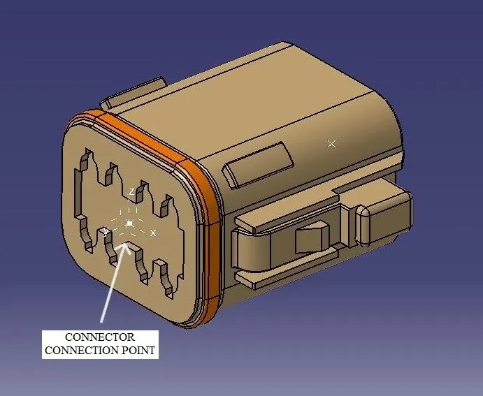
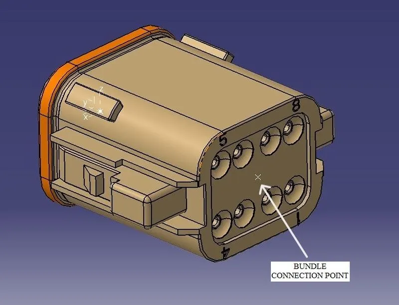
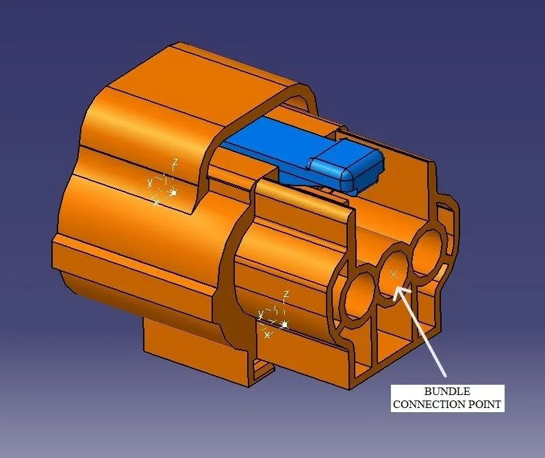
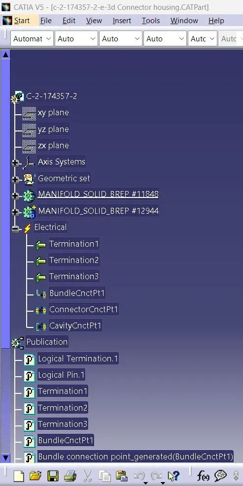
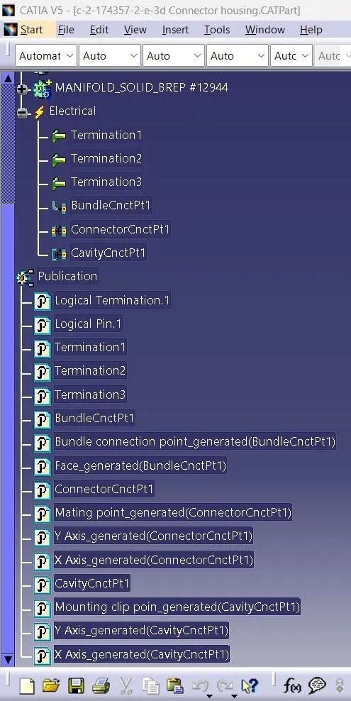
- Then after coverting all cad models into electrical parts need to create bundle point, mating point/axis, cavity connection point/axis for their assembly.
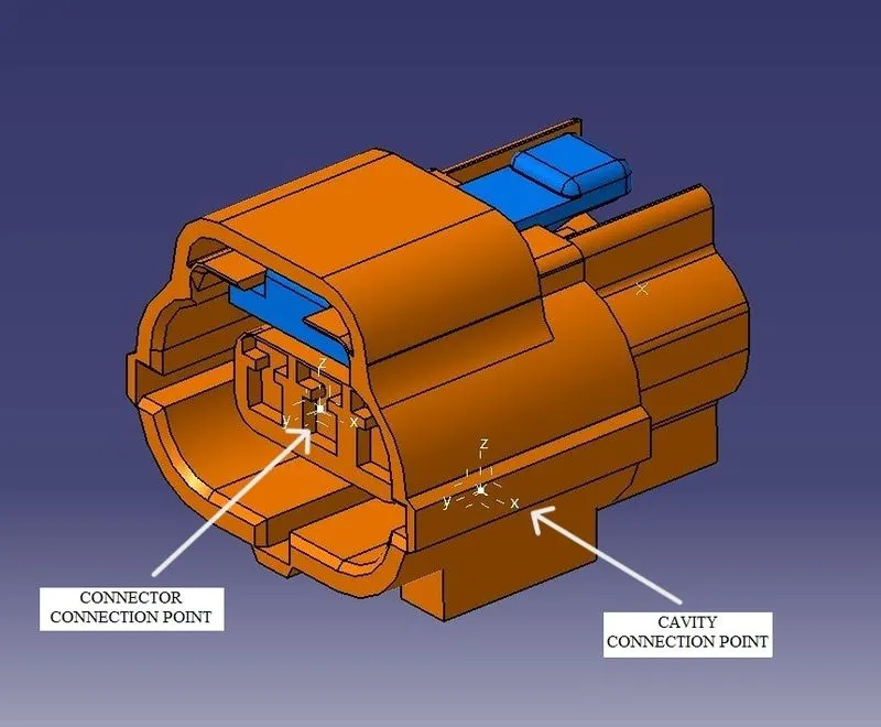
- Whenever we crating axis on that point we must need to give Y direction at that direction where bundle or wire will pass then X direction at that direction where locking shape is having and remain Z direction at remaining direction.
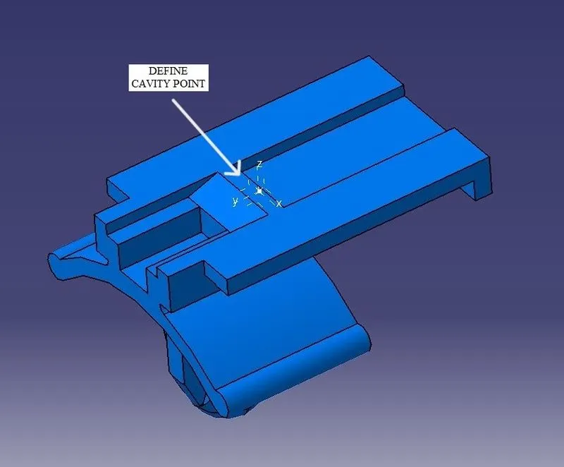
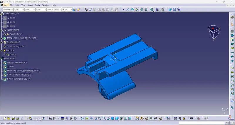
- In below side we can understand where bundle point, mating point and cavity connection point is. For mounting clip we need to used cavity connection point command to connector where mounting clip gonna assemble and in mounting clip need to use define cavity command for assemble.
PLUG CONNECTOR WITH FEATURE COMMAND TREE:
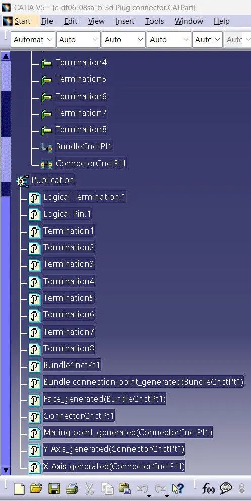
CONNECTOR HOUSING WITH FEATURE COMMAND TREE:
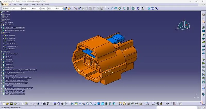
MOUNTING CLIP WITH FEATURE COMMAND TREE:
CONCLUSION: In this challenge i have learned about how to download CAD models, how to define electical connectors, what is bundle and connector points.