Week 9 - Challenge 2 - Switch Bezel Design
SWITCH BEZEL DESIGN:
Notations:
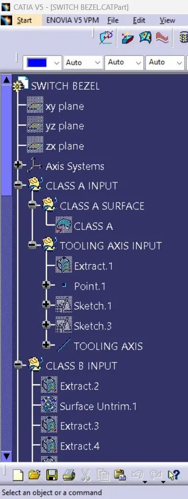
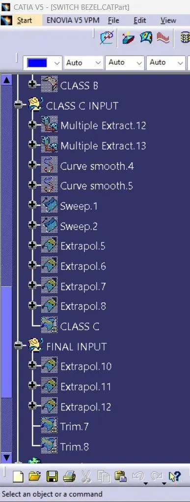
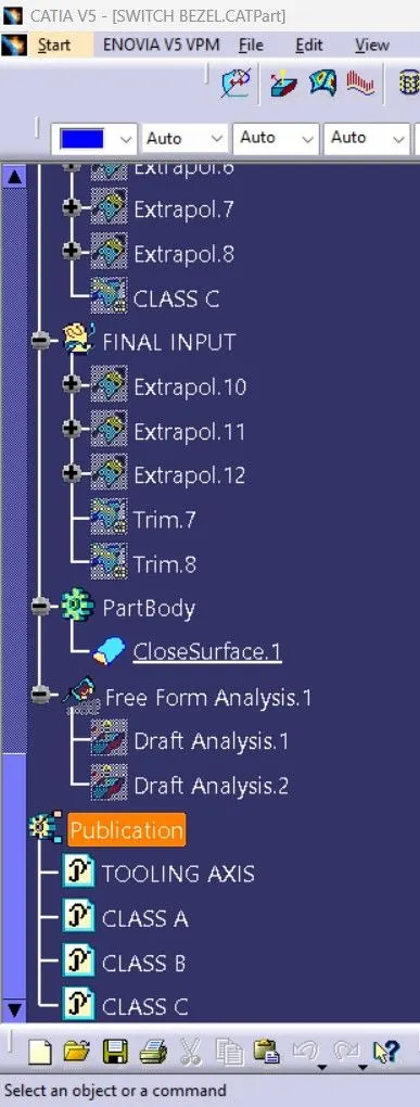
- Maintained proper tree stucture and gave proper name to geometric set.
- All sketches and surfaces have made under geometric set and close surface command is under part body.
- Also publicated tooling axis, class A, B and C surface and took thickness of component 2.5mm.
Design steps:
- Before making any plastic product surface design we need to create tooling axis and with the help of different surfaces we can create tooling axis and for tooling axis, Bisecting command is used.
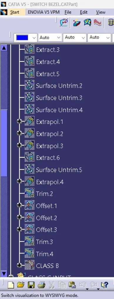
- After making tooling axis with the help of bisecting command then need to create Class B surface with help of Class A surface. And use of extract, offset, trim, extrapolate, untrim and etc. command we can create Class B surface.
- After Class B surface with help of multi-extract we can generate boundry line of Class A surface which help to create Class C surface and for smooth and curvature surface we used smooth curvature command on generated boundry line.
- After that need to join Class A and Class C surface for trim with Class B surface to get proper final body and after that creating final solid body need to use Close surface command.
Tooling axis creating steps:
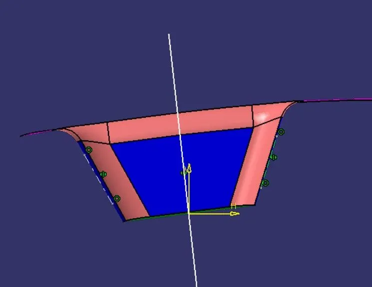
- For tooling axis first need to check surfaces where we can create tooling lines and for like this complex surface need to create sketches and then with the help of bisecting we can create tooling axis.
- We can see below which surface i selected for line and how sketch has been drawn.
- After this second line on other side surface need to create which we can see below side.
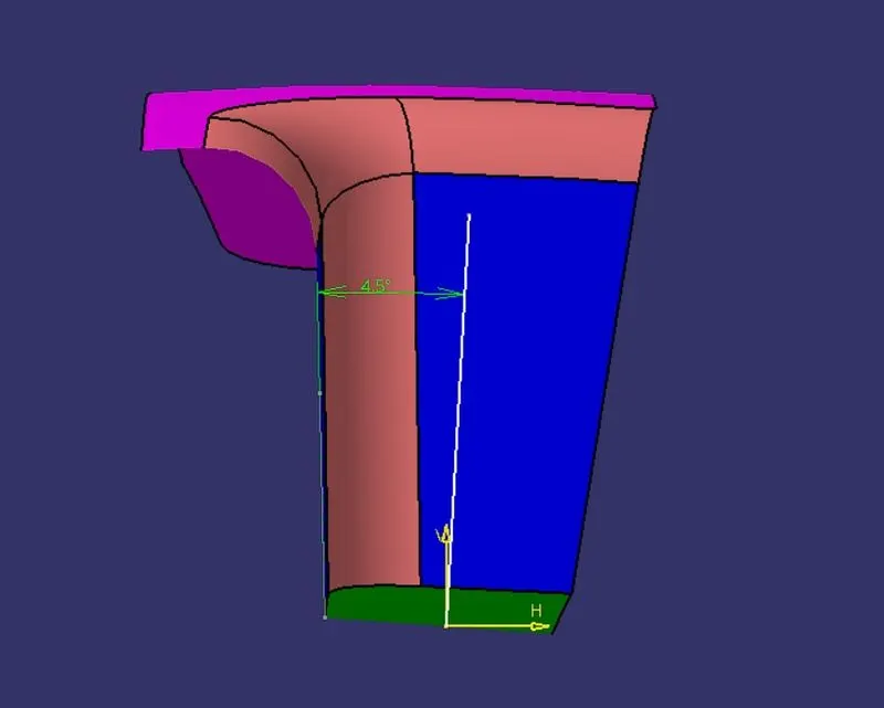
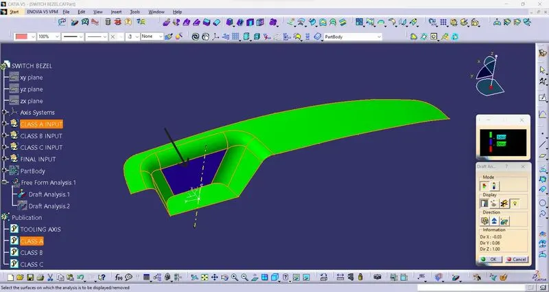
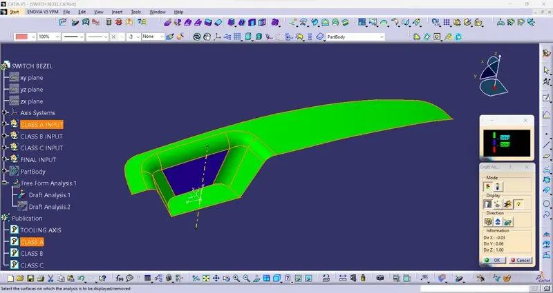
- Generally for plastic product we use 3° to create draft same that for creating tooling line of single surface we use 3° but in this design i used 4.5° line from surface cause we can see below that surface on Class A surface is alreay is negative direction.
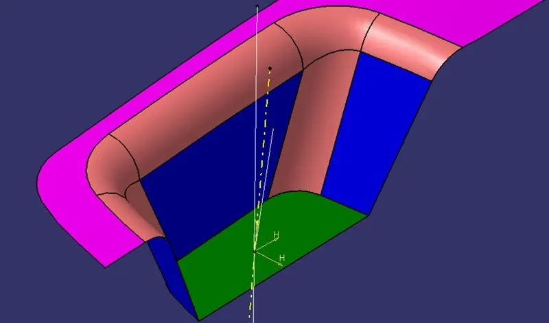
- Then after creating this two lines with help of bisecting line command we can create tooling axis and in below side picture shows yellow line which is tooling axis.
DRAFT ANALYSIS CLASS A SURFACE:
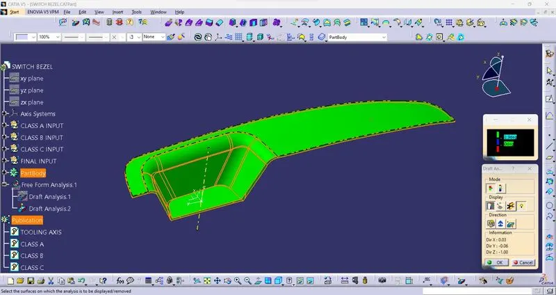
DRAFT ANALYSIS FINAL BODY:
EXPANDED FEATURE COMMAND TREE:
DIFFERENT TYPES OF VIEWS:
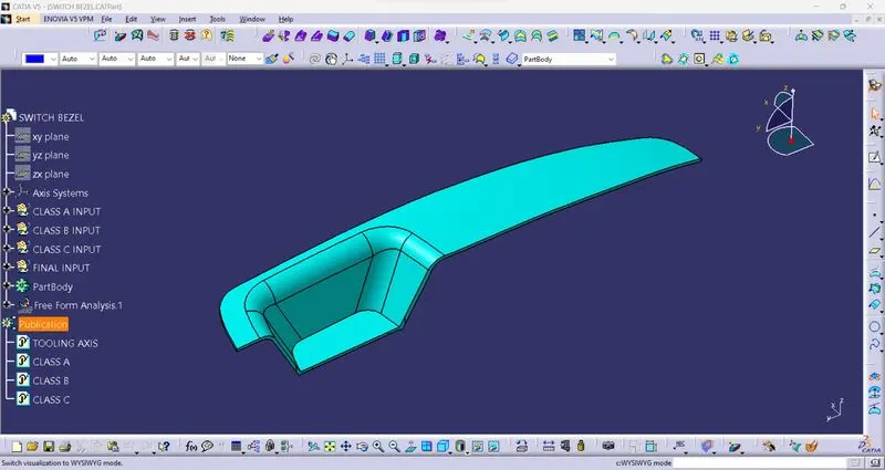
Isometric view:
Front view:
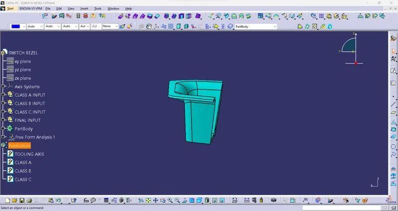
Side view:
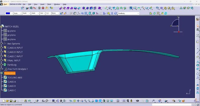
Top view:
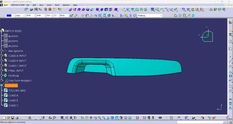
Conclusion: In this challenge i have leared how to create tooling axis on complex shape surface and also have learned how to use multi extract command and smooth curvature command for creating smooth surface.