Week 10 - Challenge 3 - Door Trim Lower with Engineering Features
DOOR TRIM LOWER:
Notations:
- Used Positioned sketch and Sketches are also iso-contrained.
- Used the given points in the model to create the locators and Heat stakes
- Maintained proper Tree structure with proper name for Geometric set and Body.
- Also all sketches has created under Geometric set and solid command in Body.
Locators and heat stakes:
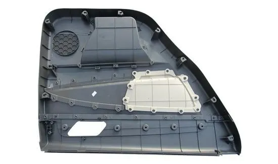
Tooling axis:
- For door trim lower design no need to use bisecting command or no need to create new sketch for tooling axis as per it's Class A Surface design we can use Y direction line as tooling axis.
- For locators and heat stakes we can also use same tooling axis for giving them draft and for draft analysis. Below we can understand how Y direction tooling axis look like with draft analysis.
DRAFT ANALYSIS:
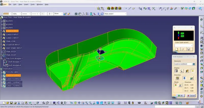
Class A Surface draft analysis
- For Class A surface in draft analysis 3° draft is used and tooling axis we can understand in below picture.
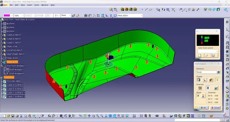
Final body draft analysis
- Also for Final body i used 3° in draft analysis for final close body which has 2.5mm thickness below picture we can understand how it look like.
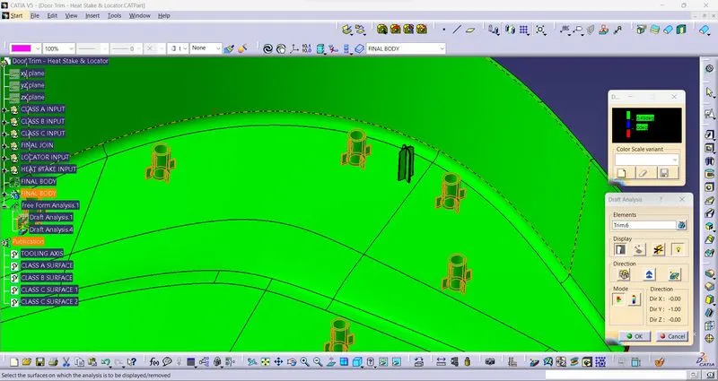
Locator and heat stake draft analysis:
- For locators and heat stakes 0.5° is used for draft analysis and below we can see how it look like.
DIFFERENT TYPES OF VIEW:
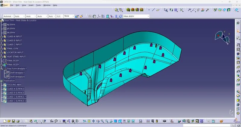
Isometric view:
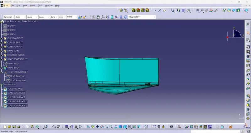
Front view:
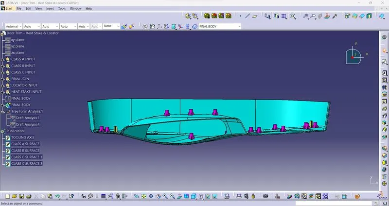
Side view:
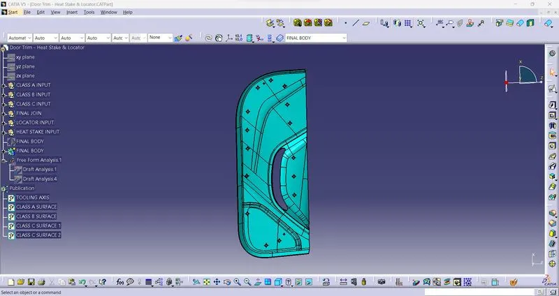
Top view:
Conclusion: In this challenge i have learned how to create locators and heat stakes on different points.