Week 9 - Challenge 3 - Bumper
BUMPER DESIGN:
Notations:
- Maintained proper tree stucture and gave proper name to geometric set.
- All sketches and surfaces have made under geometric set and close surface command is under part body.
- Also publicated tooling axis, class A, B and C surface and took thickness of component 3mm.
Design steps:
- For making this bumper having liitle different kind of steps like we saw in previous challenges for creating Class B surface we need to use extract and extrapolate on every surface but in this type of complicated Class A surface we need to first direct use offset as we require and then need to solve the errors.
- After offseting Class A surface to 3mm need to redesign some surfaces and give good asthetic look which look like Class A surface and for solving errors or creating new surface need to use extract, multiple-extract, extrapolate, split, trim, multi-section surface, sweep and etc.
- After creating Class B surface with the help of Class A surface's boundary need to create boundary on Class A surface and sweep into different direction which depend of surface style. On some surface we can use with reference surface or with draft direction option in sweep.
- After creating all three Class A,B and C surface need to join Class A and Class C surface with each other and then we can trim it with Class B surface and then at the end we get proper close surface without thickness. Then for making it solid need to use close body surface command then it'll create solid body with 3mm thickness.
Tooling Axis:
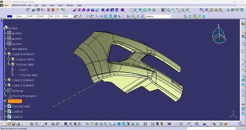
- For this kind of design we can directly use a direction on behalf of design which we can check with draft analysis or we can create a point in center of gravity using measure inertia and then with line command can create line in center center of surface design
- Below we can see i used meausre inertia command to create point on center and then create yellow line in X direction which is tooling axis.
DARFT ANALYSIS:
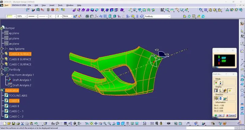
Class A surface draft analysis:
Final body draft analysis:
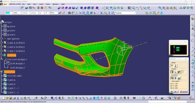
- In upper pictures it's look like same but in feature command tree we can understand that first is Class A surface draft analysis and second is final body draft analysis.
DIFFERENT TYPES OF VIEWS:
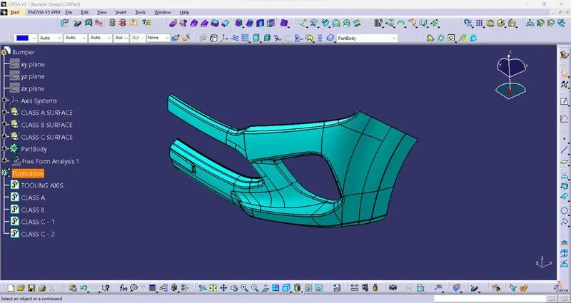
Isometric view:
Front view:
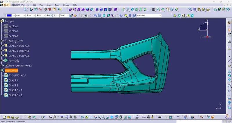
Top view:
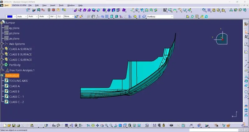
Side view:
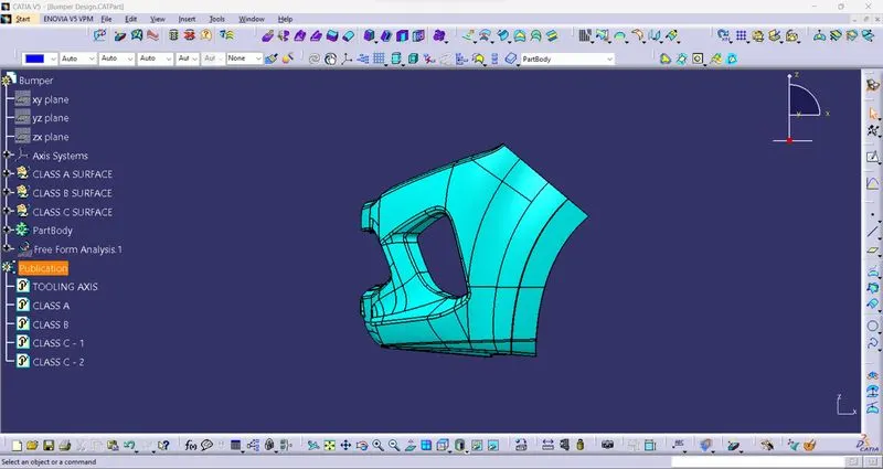
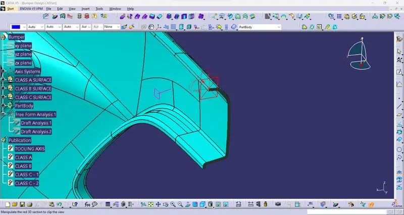
Section view: (For understanding it's close and having thickness)
Conclusion: In this challenge i've learned how to create Class B and Class C surface when Class A surface having complex shape and got to know how to use Multi-section surface and Multiple-extract with complementary mode.