Week 10 - Challenge 1- Attachment Feature Creation (Ribs & Screw Boss)
DOOR HANDLE DESIGN:
Notations:
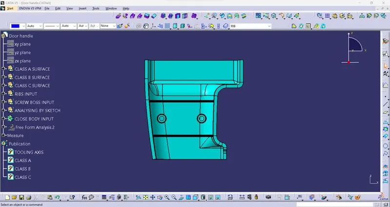
- Maintained proper tree stucture and gave proper name to geometric set.
- All sketches and surfaces have made under geometric set and close surface command is under part body.
- Also publicated tooling axis, class A, B and C surface and took thickness of component 3mm.
- Also have used Surface and Boolean features to create ribs and screw boss.
Design steps for ribs:
- For making some ribs on close solid body first we need to make close body with help of Class A surface. After making final solid body need to sketch on body where we want ribs, Using of surface we can create seprate surface of rib.
- After making of seperate surface of ribs need to use union trim and remove trim command of boolean features, Where at the end we can get one single body with ribs and there are few design factors which we can see below.
Design factors for rib:
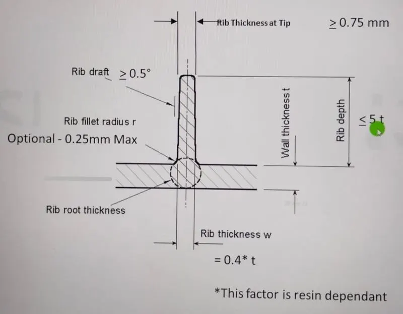
- Draft - 0.5 degree
- Thickness - 0.4 x thickness
- Height - 5 x thickness
- Radius of rib - 0.25 max.
- As we can see upper side picture it shows the factors and also have explained below of picture how value can be taken.
Design steps for screw boss:
- For making screw boss, It's also need final body to make it after making final body we can create sketch wherever we want and then after we can use pad or shaft command to create solid shape.
- For this again also need to use boolean features like union trim and remove trim which can help to make single body and connect screw boss to final body. For screw boss also having design factors which we can see below.
Design factors for screw boss:
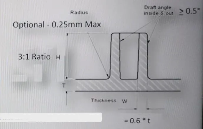
- Internal diameter - As per thread size (Like usign M8 then take 6.8 which we get from their pitch ) or ( Like usign M6 then take 5 which we get from pitch )
- Outer diameter - {(Thickness x 0.6) x 2}+ inetrnal diameter (Like 6.8 or 5 etc.)
- Draft - 0.5
- radius - 0.25 max.
- Height - 3 x internal diameter (3:1 ratio)
- As we can see upper side picture it shows the factors and also have explained below of picture how value can be taken.
Tooling axis and draft analysis:
- For this challenge i have made 3 types of tooling axis where i need to analys which is better for molding operation. And below side picture shows three of axis but at the end i took one tooling axis which is created on normal to surface command.
- Three of them having some draft problems in Class A surface cause Class A surface might have some problems that's why i had to took one tooling axis which is more preferable below pictures see difference.
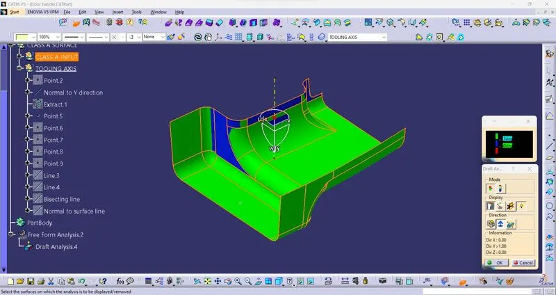
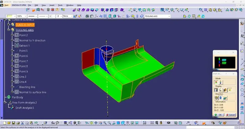
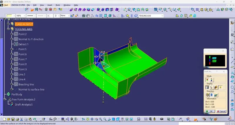
- As we can understand in feature tree command three of them having different tooling axis and i took last one which normal to surface and same tooling axis i'll use for final body draft analysis.
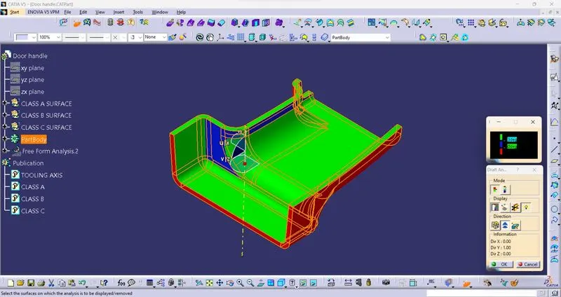
Draft analysis on final body:
Rib root thickness:
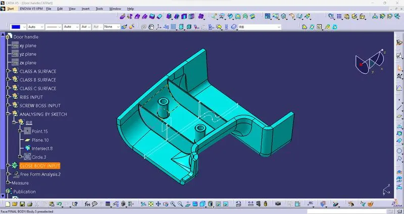
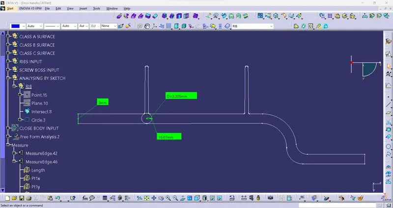
- For rib root thickness first need to make ribs on proper surface then need to use intersection which can generate intersection on final body and on behalf of that we can create rib root thickness.
- Like below shown picture we can understand how on intersection sketch used tritanget circle command for making rib root thickness and also can see dimension of rib root thickness.
Draft analysis of ribs and screw boss:
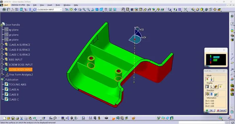
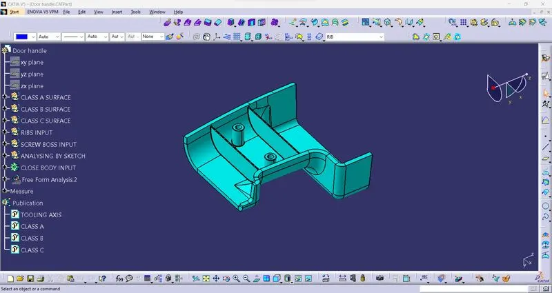
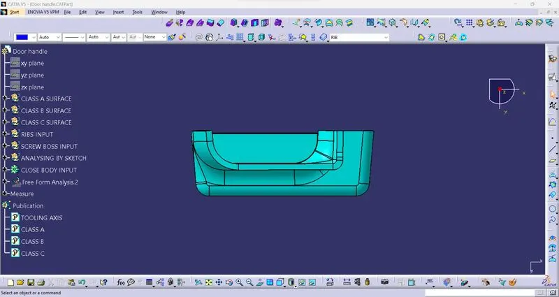
DIFFERENT TYPES OF VIEWS:
Isometric view
Front view
Side view
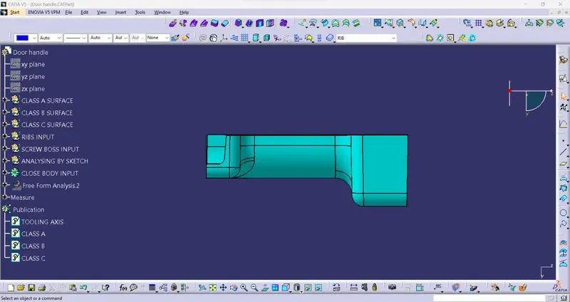
Top view
Conclusion: In this challenge i have learned about how to make ribs and screw boss with their design factors and also how to give draft on them.