Week 8 - Simulating Cyclone separator with Discrete Phase Modelling
Aim:- To perform analysis on cyclone separator and calculate the separation efficiency and pressure drop.
Objective:-
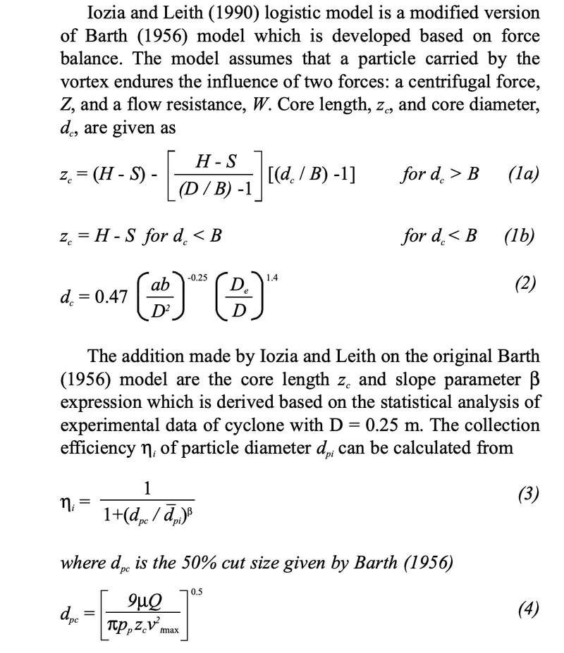
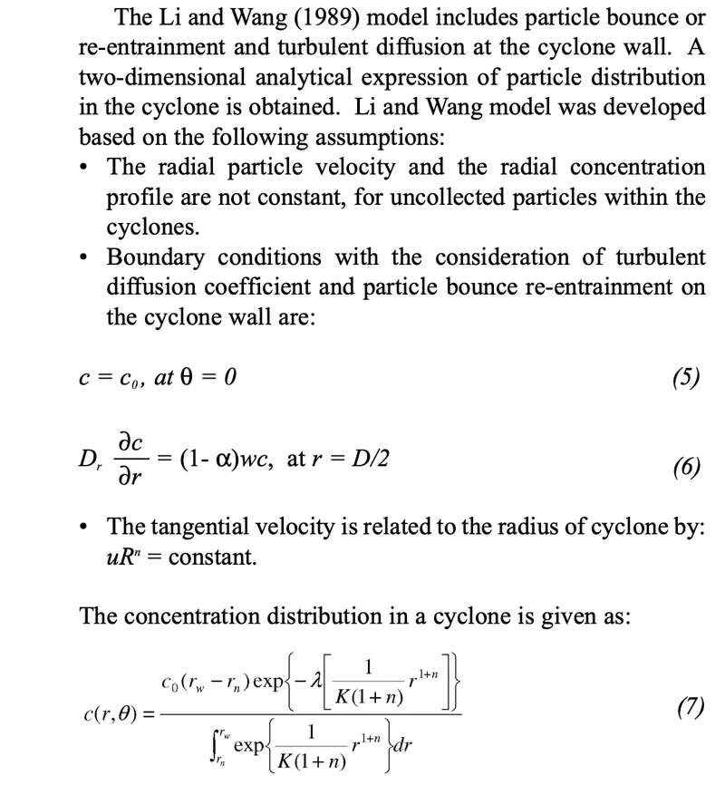
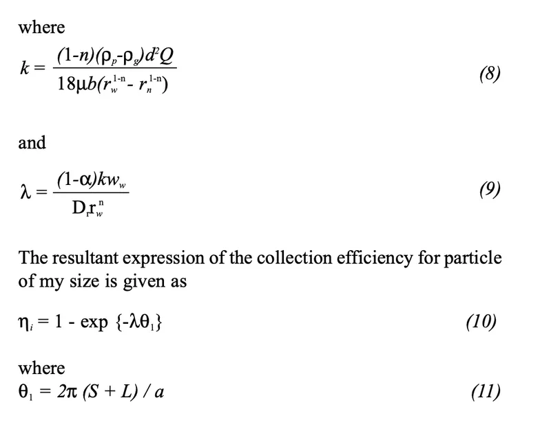
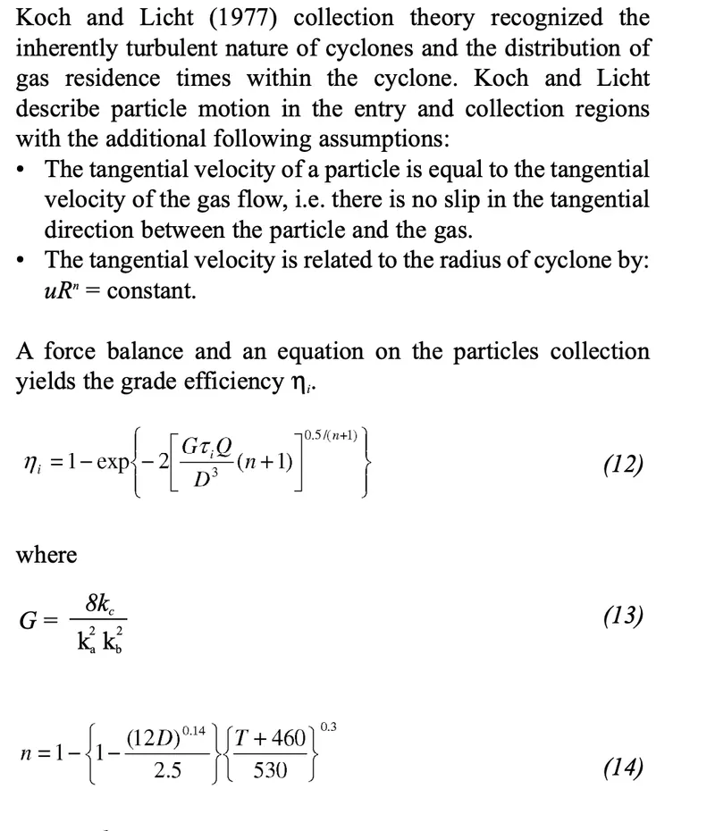
- To write a few words about any four empirical models used to calculate the cyclone separator efficiency.
- To perform an analysis on a given cyclone separator model by varying the particle diameter from 1 μm to 5 μm and calculate the separation efficiency in each case. Discuss the results. [Use both the velocity's as 3m/sec.]
- To perform an analysis on a given cyclone separator model by varying the particle velocity from 1 m/sec to 5 m/sec and calculate the separation efficiency and pressure drop in each case. Discuss the results. [Use particle diameter size as 5 μm for all cases & keep flow velocity same as particle velocity]
Boundary Conditions:-
Inlet and wall:- Reflect
Outlet(Top):- Escape
Outlet(Bottom/dustbin) - Trap
Principles of Cyclone Separator:
In a cyclone separator, centrifugal force is used to separate the solids from fluids. The separation process depends not only on the particle size but also on the density of particles. Depending on the fluid velocity, the cyclone separator can be used to separate all types of particles. It is also possible to allow fine particles to be carried by the fluid.
Construction of Cyclone Separator:
The construction of a cyclone separator is shown in Figure. It consists of a short vertical, cylindrical vessel with a conical base. The upper part of the vessel is fitted with a tangential inlet. The outlet (solid outlet) is arranged at the base. A fluid outlet is provided at the center of the top portion, which extends inwardly into the separator. Such an arrangement prevents the air from short-circuiting directly from the inlet to the outlet of the fluid.
Working of Cyclone Separator:
The solids to be separated are suspended in a stream of gas (usually air). Such a feed is introduced tangentially at a very high velocity so that rotary movement takes place within the vessel. The centrifugal force and vortexing throw the solids to the walls. As the speed of air diminishes, the particles fall to the conical base and are discharged through the solid outlet. The fluid (air) can escape from the central outlet at the top.
Uses of Cyclone Separator:
- It is used to separate the solids from gases.
- It is also used for the size separation of solids in liquids.
- It is used for separating the heavy or coarse fraction from fine dust.
1. To write a few words about any four empirical models used to calculate the cyclone separator efficiency.
IOZIA AND LEITH MODEL:
LI AND WANG MODEL :
KOCH AND LICHT MODEL :
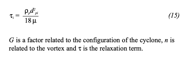
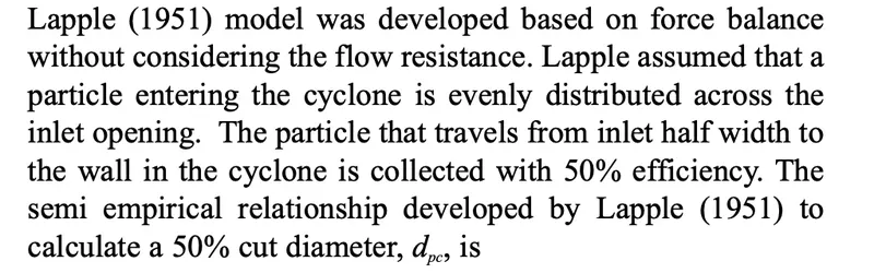
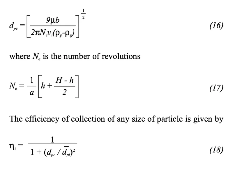
LAPPLE MODEL :
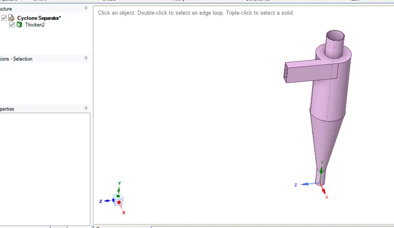
Geometry:
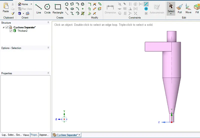
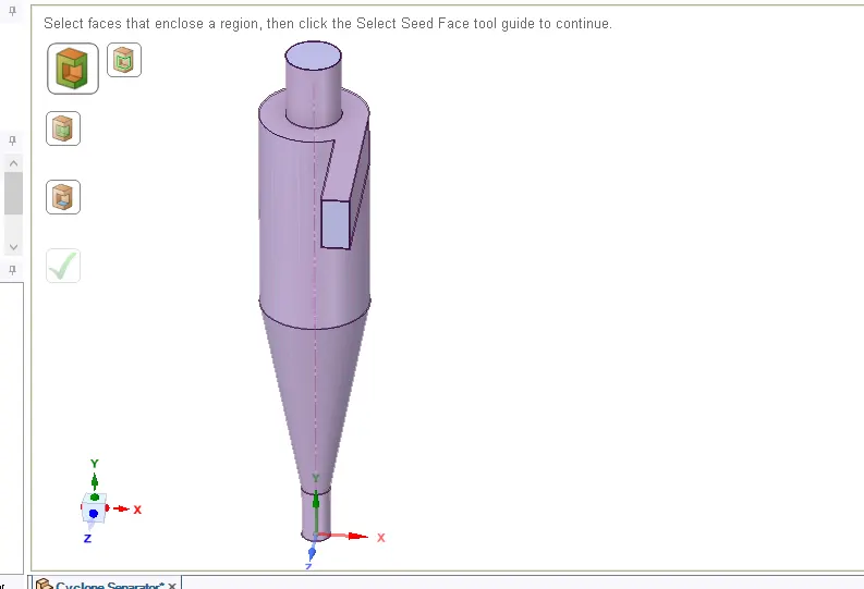
First step import the model in spaceclaim.
After that extract the volume of the model.
Geometry is same for all 10 cases.
Meshing:
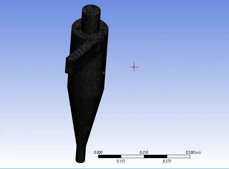
mesh size 6mm
Setup and Solution:
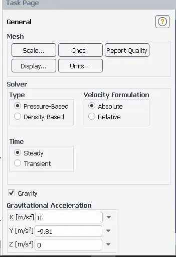
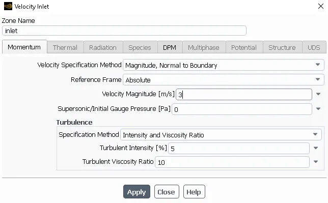
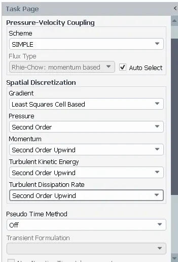
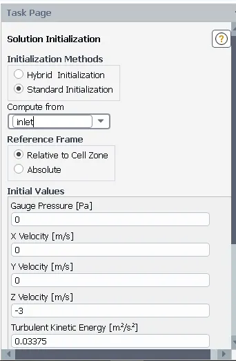
Setup is same for all the cases.
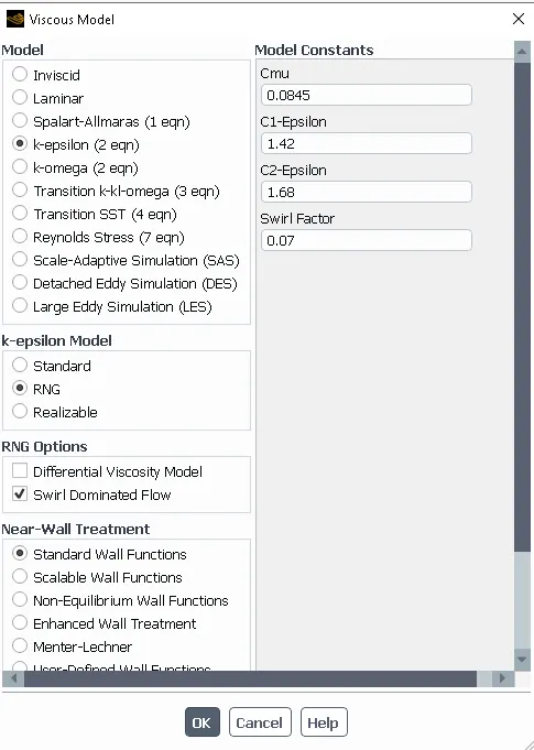
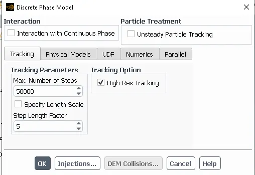
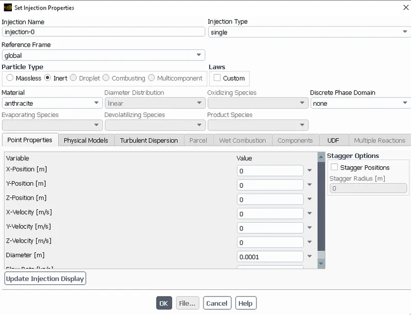
2. To perform an analysis on a given cyclone separator model by varying the particle diameter from 1 μm to 5 μm and calculate the separation efficiency in each case. Discuss the results. [Use both the velocity's as 3m/sec.]
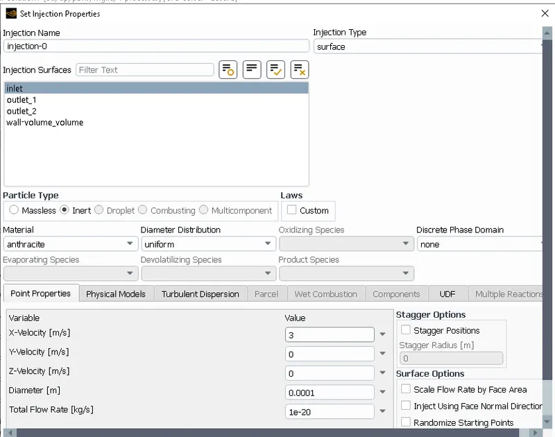
Case 1:
Diameter: 1 micrometer
Velocity: 3 m/s
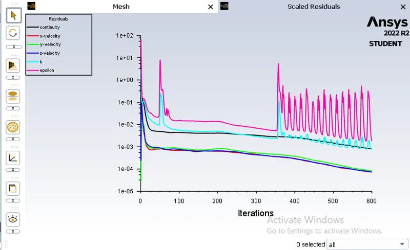
600 Iteration
Separation Efficiency = No. of particles Trapped/No. of particles Tracked
Residual Plot:
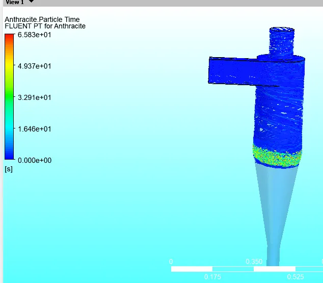
Contour Plot:
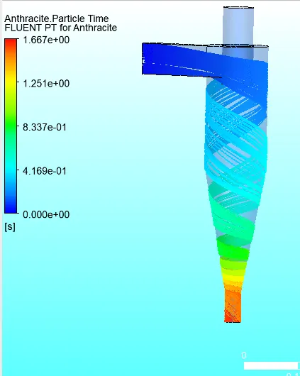
Separation Efficiency = 102/170 *100 = 60%
CASE 2:
Diameter: 2 micrometer
Velocity: 3 m/s
600 Iteration
Separation Efficiency = No. of particles Trapped/No. of particles Tracked
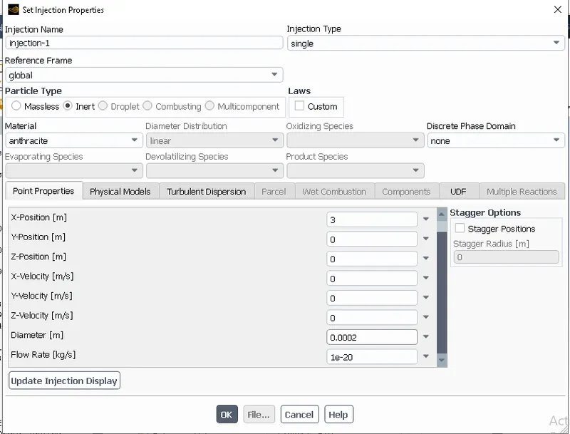
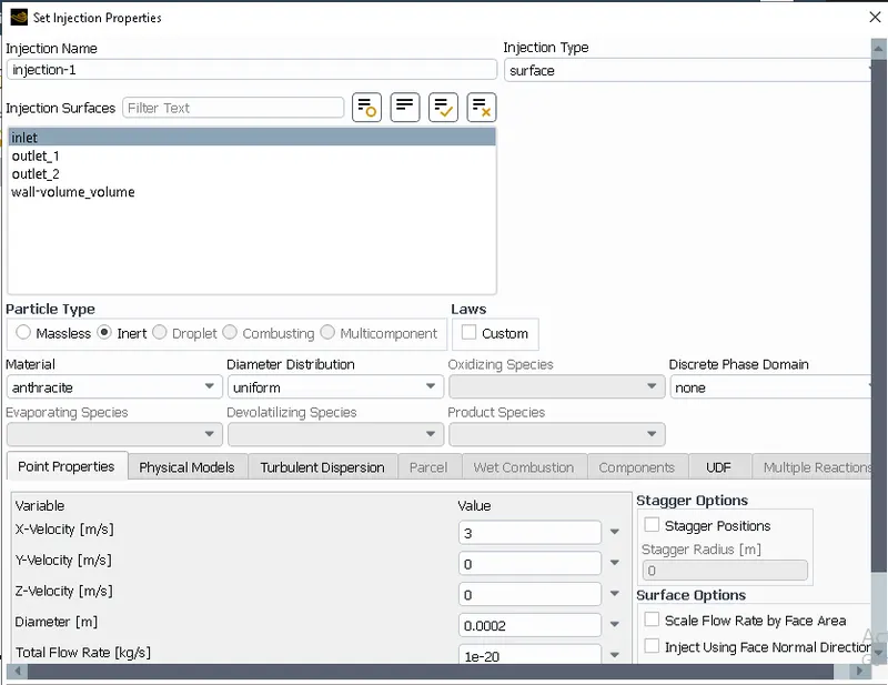
Residual Plot:
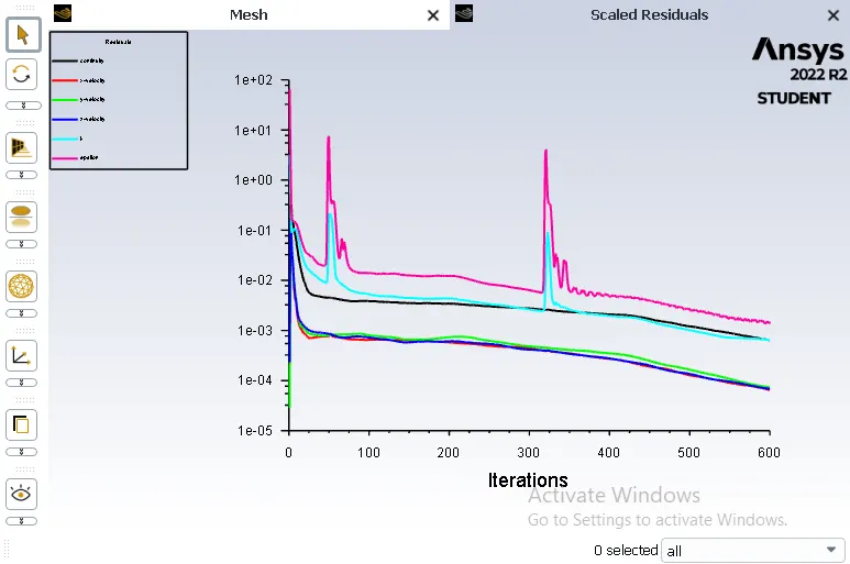
Contour Plot:
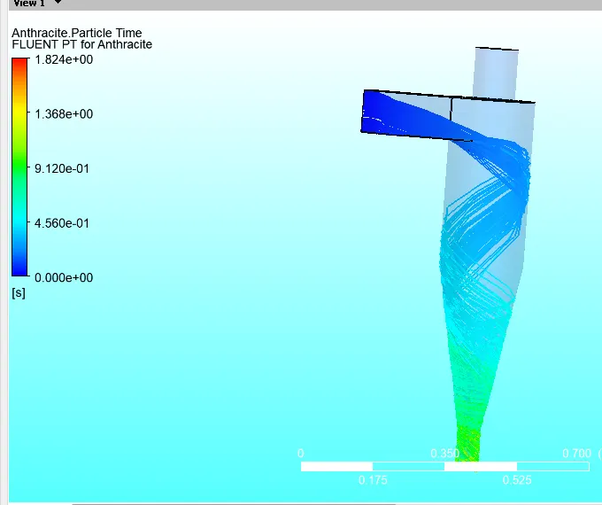
Separation Efficiency = 114/170 *100 = 67.05%
Case 3:
Diameter: 3 micrometer
Velocity: 3 m/s
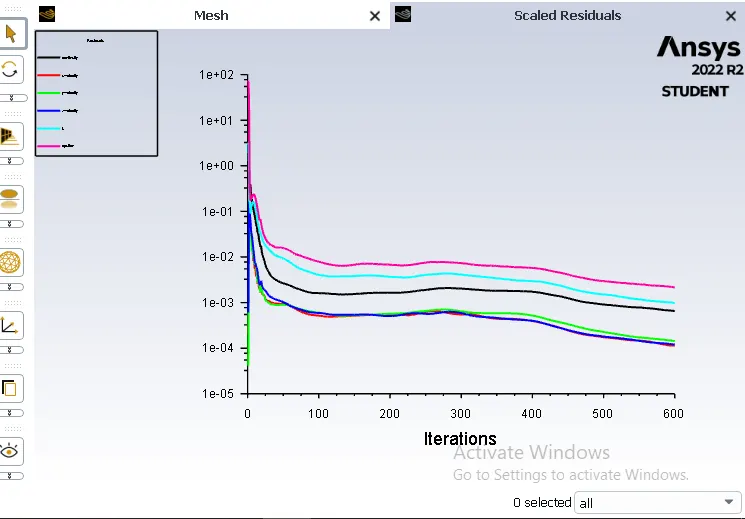
600 Iteration
Separation Efficiency = No. of particles Trapped/No. of particles Tracked
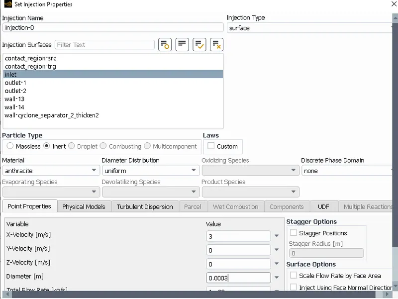
Residual Plot:
Contour Plot:
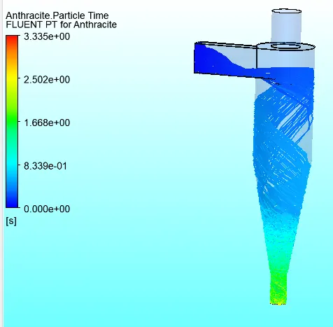
Separation Efficiency = 130/170 *100 = 76.47%
Case 4:
Diameter: 4 micrometer
Velocity: 3 m/s
600 Iteration
Separation Efficiency = No. of particles Trapped/No. of particles Tracked
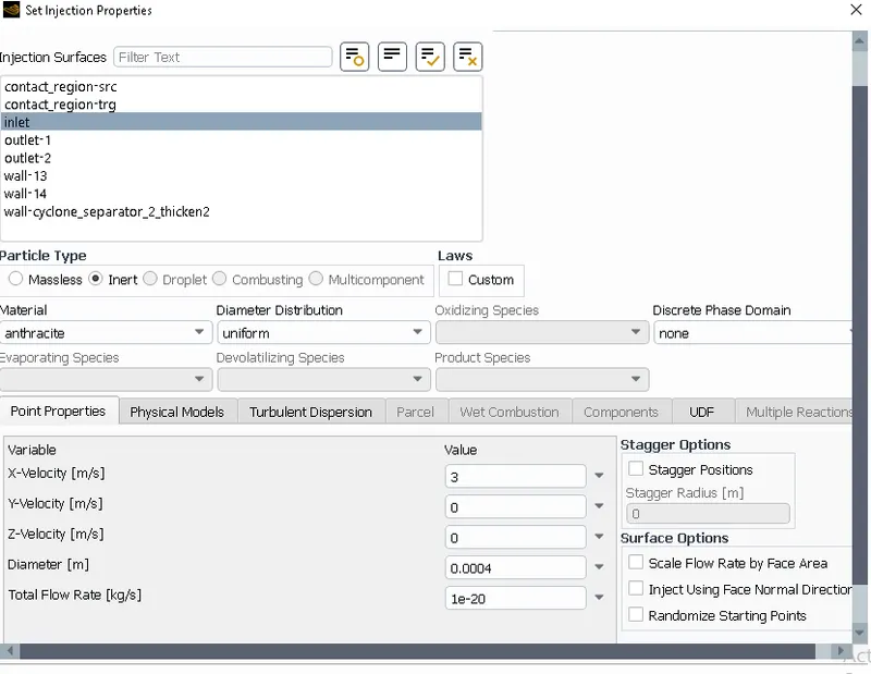
Residual Plot:
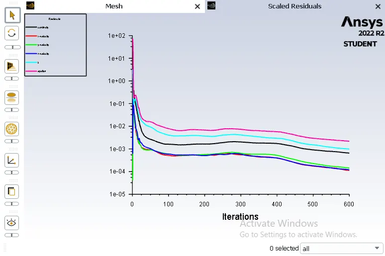
Contour Plot:
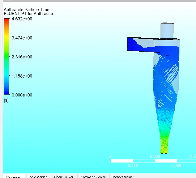
Separation Efficiency = 150/170 *100 = 88.23%
Case 5:
Diameter: 5 micrometer
Velocity: 3 m/s
600 Iteration
Separation Efficiency = No. of particles Trapped/No. of particles Tracked
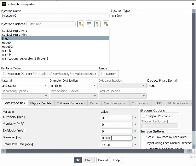
Residual Plot:
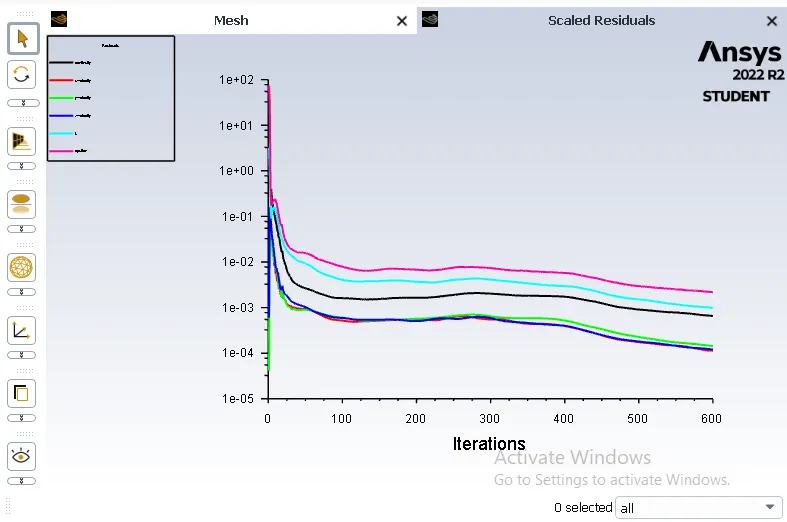
Contour Plot:
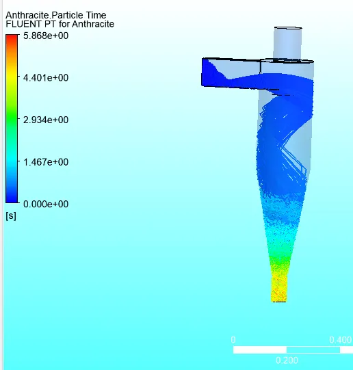
Separation Efficiency = 168/170 *100 = 98.82%
3. To perform an analysis on a given cyclone separator model by varying the particle velocity from 1 m/sec to 5 m/sec and calculate the separation efficiency and pressure drop in each case. Discuss the results. [Use particle diameter size as 5 μm for all cases & keep flow velocity same as particle velocity]
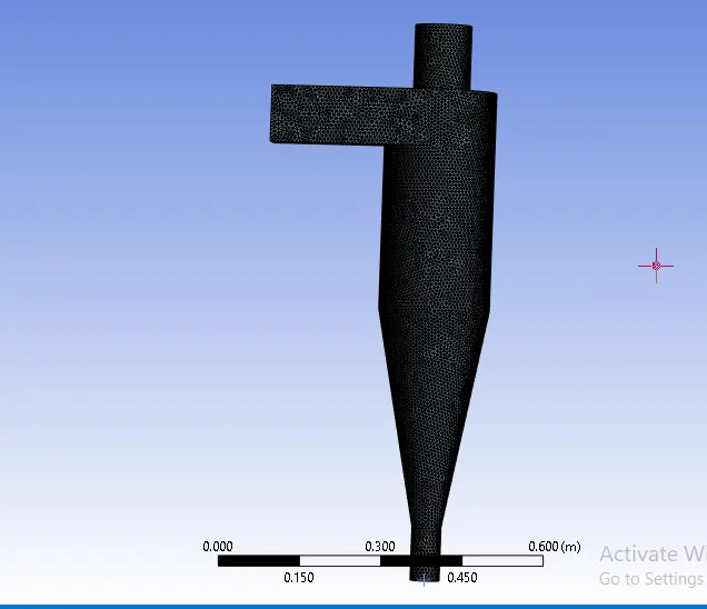
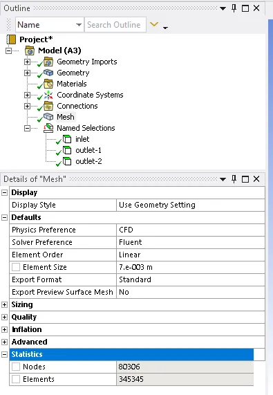
Meshing:
Mesh size 7mm
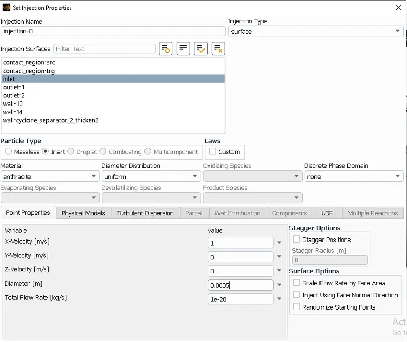
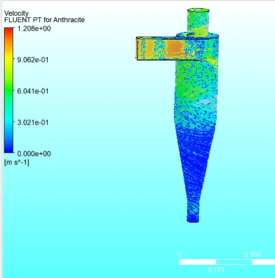
Case 6:
Diameter = 5 micrometer
Velocity = 1m/s
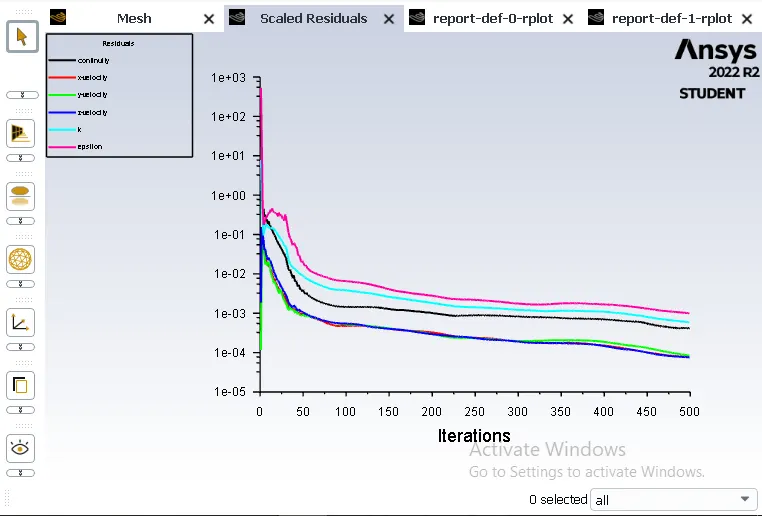
Iteration 500
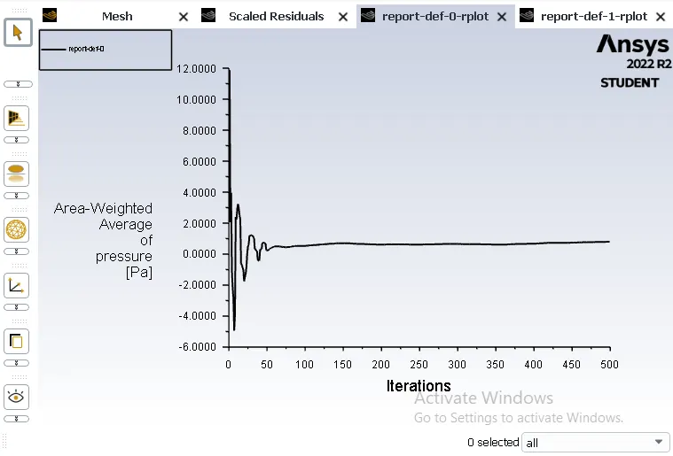
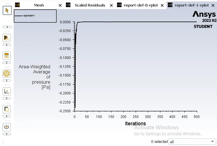
Pressure drop = Total inlet pressure - Total Outlet pressure
Residual Plot:
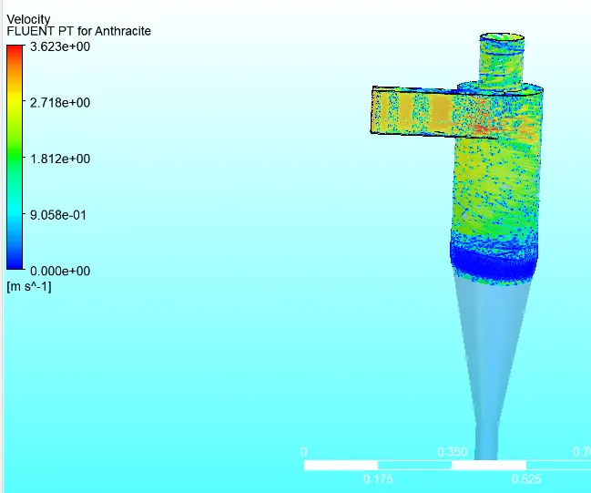
Velocity Plot:
Pressure Plot:
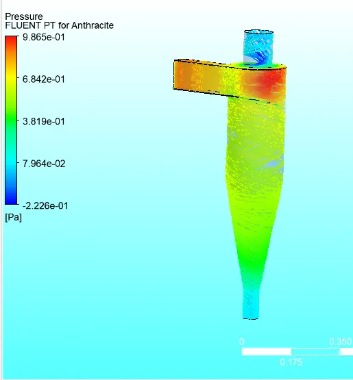
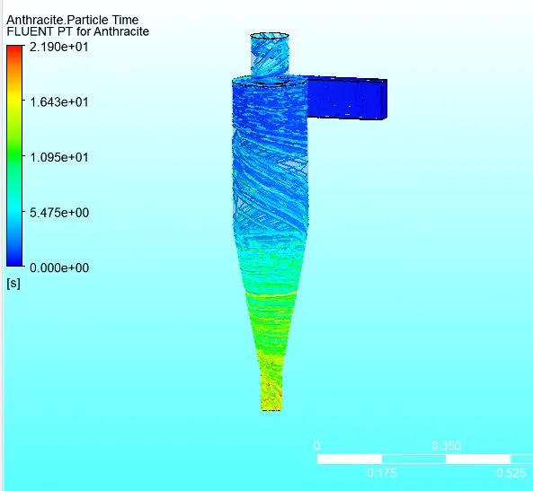
Pressure Drop = 3.6 pa
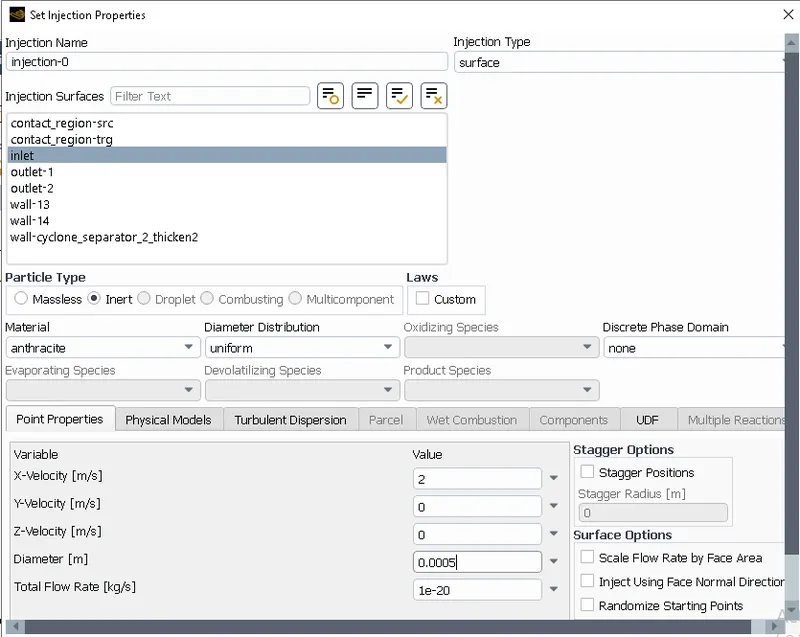
Case 7:
Diameter = 5 micrometer
Velocity = 2m/s
Iteration 500
Pressure drop = Total inlet pressure - Total Outlet pressure
Residual Plot:
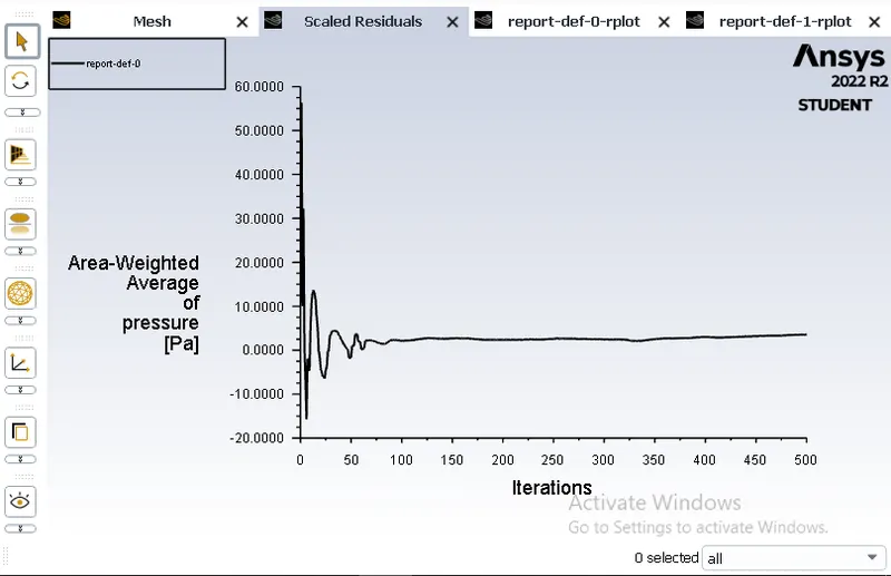
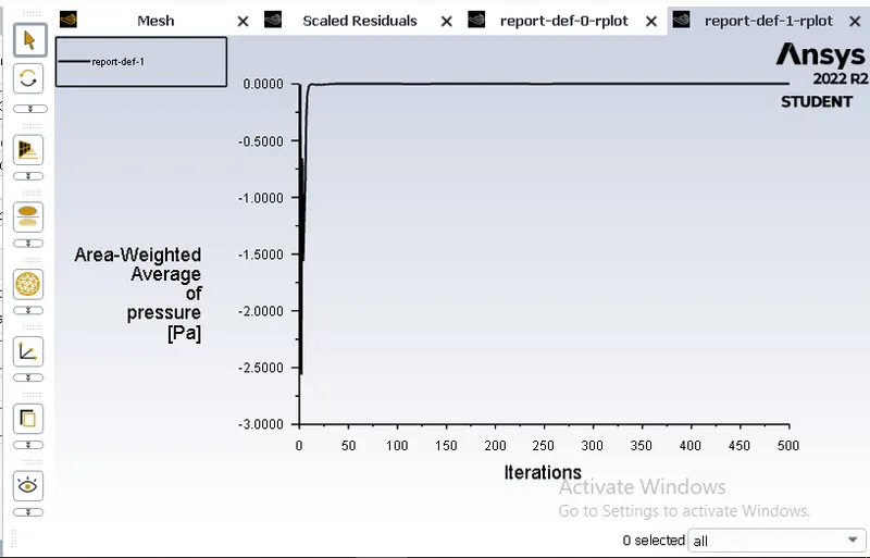
Velocity Plot:
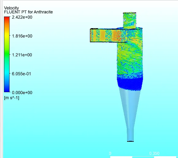
Pressure Plot:
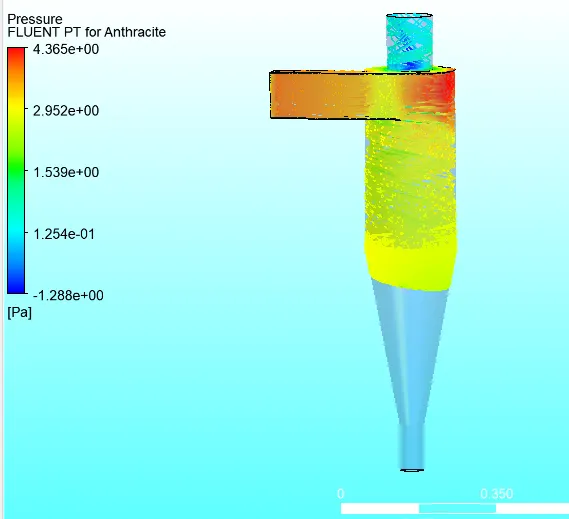
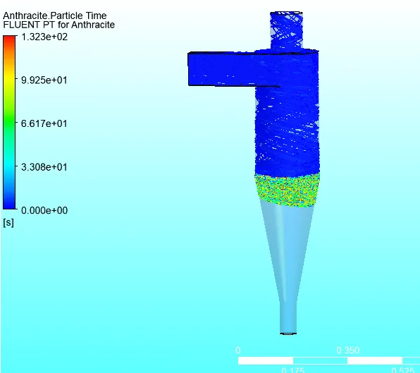
Pressure Drop = 13.7 pa
Case 8:
Diameter = 5 micrometer
Velocity = 3m/s
Iteration 500
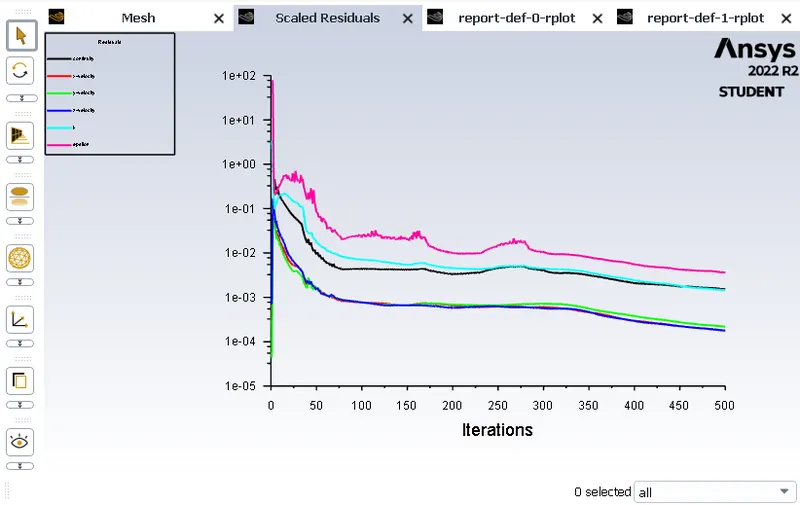
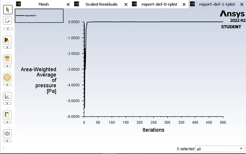
Pressure drop = Total inlet pressure - Total Outlet pressure
Residual Plot:
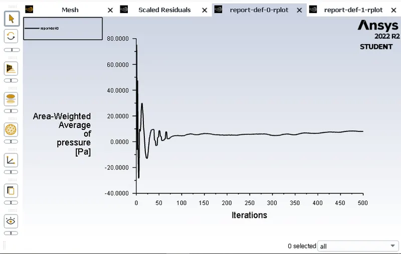
Velocity Plot:
Pressure Plot:
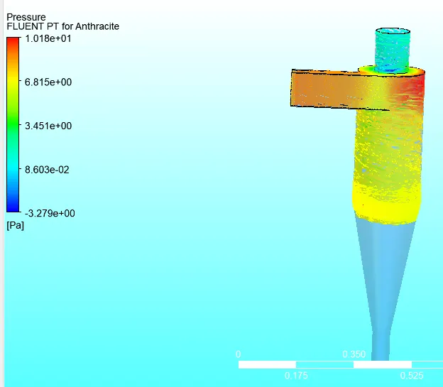
Pressure drop = 34.08 pa
Case 9:
Diameter = 5 micrometer
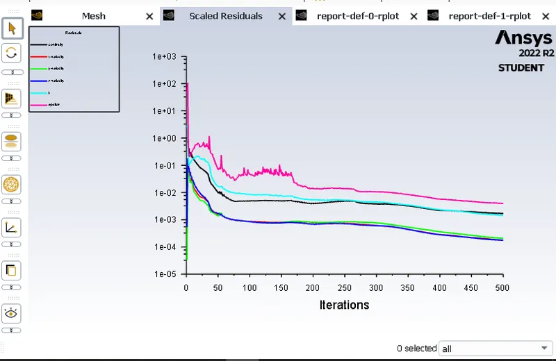
Velocity = 4m/s
Iteration 500
Pressure drop = Total inlet pressure - Total Outlet pressure
Residual Plot:
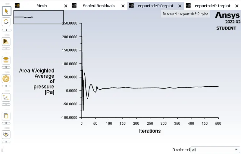
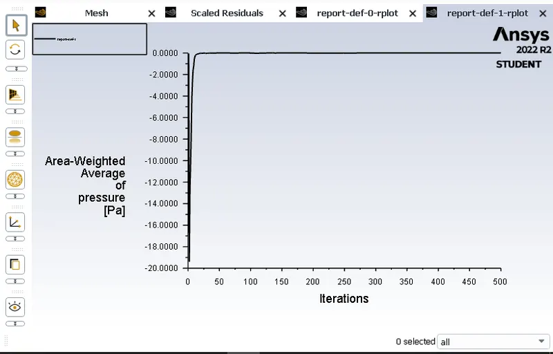
Velocity Plot:
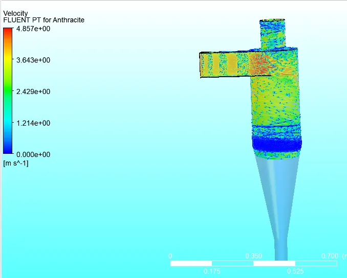
Pressure Plot:
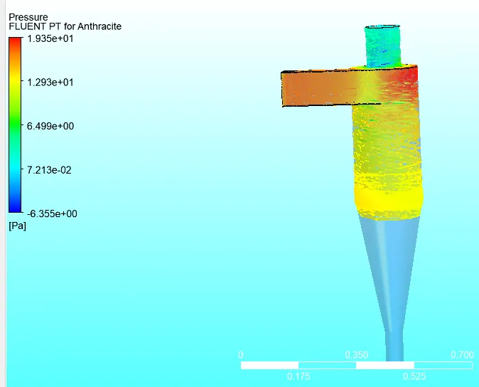
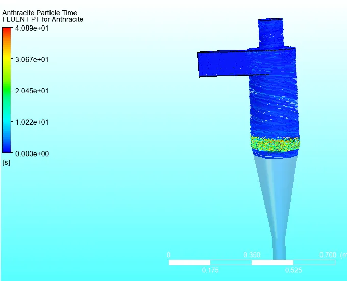
Pressure drop = 68.05 pa
Case 10:
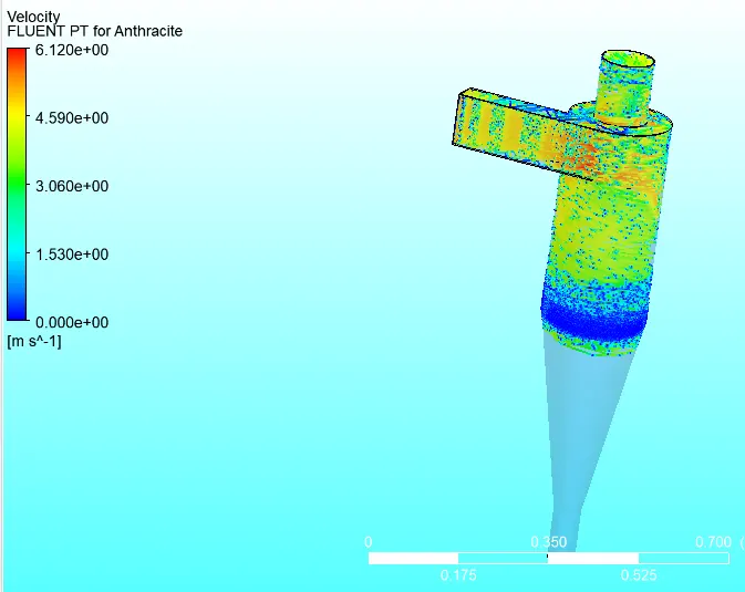
Diameter = 5 micrometer
Velocity = 5m/s
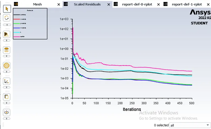
Iteration 500
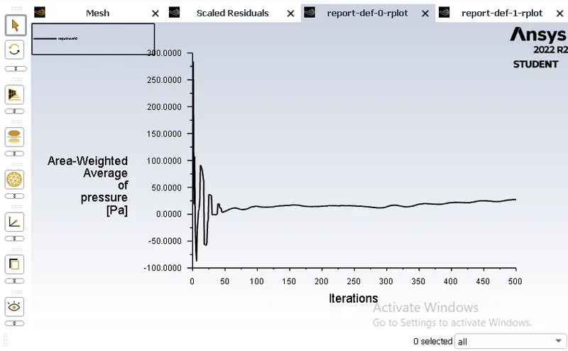
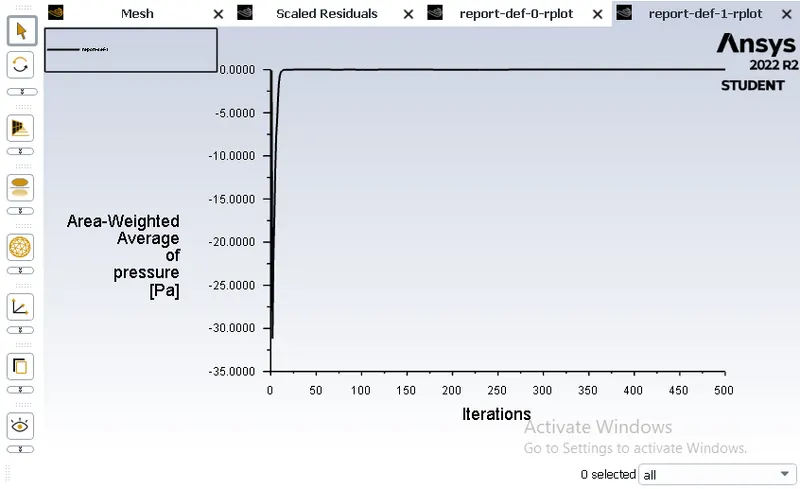
Pressure drop = Total inlet pressure - Total Outlet pressure
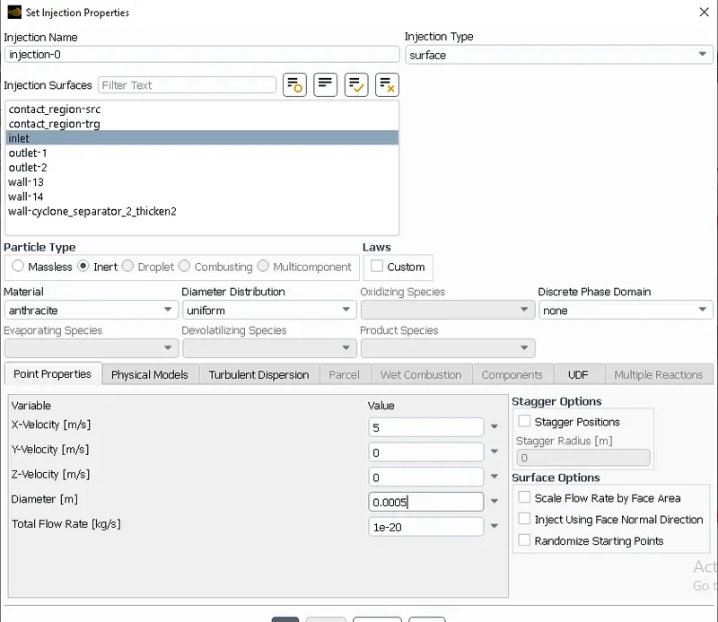
Residual Plot:
Velocity Plot:
Pressure Plot:
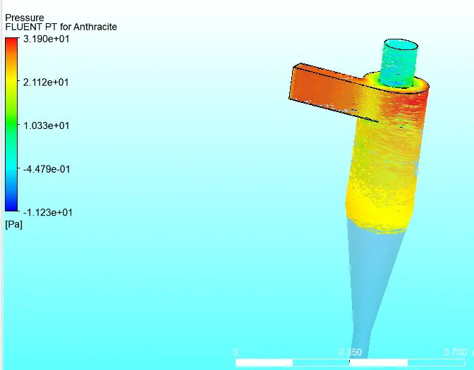
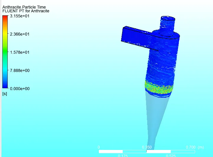
Pressure drop = 87.06
Conclusion:
1. We successfully satisfied all the criteria which is require in this case.
2. We successfully plot the required contours
Reference: