Week 9 - Parametric study on Gate valve.
Aim: For this challenge, you will have to perform a parametric study on the gate valve simulation by setting the opening from 10 % to 80%.
- Obtain the mass flow rates at the outlet for each design point.
- Calculate the flow coefficient and flow factor for each opening and plot the graph.
- Discuss the results of the mass flow rate and flow coefficient.
Introduction to Gate Valve
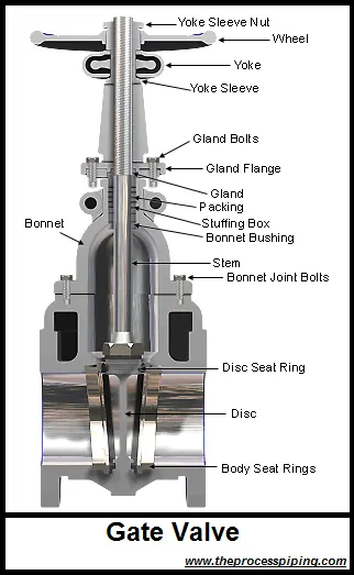
Gate valves are used to shut off the flow of fluid by inserting a rectangular gate or wedge into the path of a flowing fluid. Gate valves require very little space along the pipe axis and hardly restrict the flow of fluid when the gate is fully opened enabling gate valves to offer straightway flow with very little pressure drop. Gate valves are mostly used with larger pipe diameters (from 2″ to the largest pipelines) since they are less complex to construct than other types of valves in large sizes. More recently, however, the larger sizes have been supplemented by butterfly valves due to space limitations under which they are installed.
The gate valve, as illustrated in on the right, generally consists of a gate-like disc, actuated by a screwed stem and hand-wheel which moves up and down at right angles to the flow. In the closed position, the disc seats against two faces to shut off flow. To retain the fluid in the pipeline, a gland is provided which is supplied with some type of packing to resist leakage.
Gate Valve Working Principle
Gate valves consist of three major components: body, bonnet, and trim. The body is generally connected to the piping by means of flanged, screwed, or welded connections. The bonnet, containing the moving parts, is joined to the body, generally with bolts, to permit cleaning and maintenance. The valve trim consists of the stem, the gate, the wedge, or disc, and the seat rings.
The main operation mechanism is very simple. When the hand-wheel is turned, it rotates the stem, which is translated into the vertical movement of a gate via threads. They are considered multi-turn valves as it takes more than one 360° turn to fully open/close the valve. When the gate is lifted from the path of the flow, the valve opens and when it returns to its closed position, it seals the bore resulting in a full closure of the valve.
Gate Valve Closing Member Design
The closing member, sometimes referred as gate also, comes in a variety of designs and technologies to produce effective sealing for differing applications. There are usually two types of gate valve closing members which are having further varieties.
- Parallel Gate Valve – Use a flat gate between two parallel seats.
- Conventional Parallel Gate
- Through-Conduit Gate
- Knife Gate
- Wedge Gate Valve – Use slightly mismatched inclined gate between inclined seats.
- Solid Taper Wedge
- Split Wedge
- Flexible Wedge
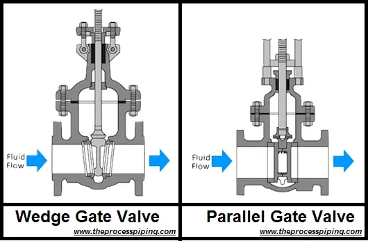
Parallel Gate Valve
Parallel gate valves have a parallel faced gate like closing member. This closing member may consists of a single disc or twin discs with a spreading mechanism in between. The force that presses the disc against the seat is controlled by the fluid pressure acting on either a floating disc or a floating seat. Because the disc slides across the seat face, parallel gate valves are also capable of handling fluids, which carry solids in suspension.
Conventional Parallel Gate Valve
In a conventional parallel slide gate valve the closure member consists of two discs with springs in between. The duties of these springs are to keep the upstream and downstream seating’s in sliding contact and to improve the seating load at low fluid pressures. The discs are carried in a belt eye in a manner that prevents their unrestrained spreading as they move into the fully open valve position.
The advantages offered by this construction include not only economy of construction but also a reduced operating effort and lower maintenance cost. The only disadvantage is a slight increase in pressure loss across the valve.
Use of Gate Valves
Gate valves meet the majority of valve requirements in process piping and are considered one of the most used valves of all the valves employed in refineries, petrochemical, and gas processing plants where pressure remains relatively low, but temperature may be very high. They are suitable for most fluids including steam, water, oil, air, and gas.
Gate valves are designed for fully open or fully closed service. They are installed in pipelines as isolating valves, and should not be used as flow control or regulating valves. When operating the valve stem, the gate moves up- or downwards on the threaded part of the stem.
Gate valves are often used when minimum pressure loss and a free bore is needed. When fully open, a typical gate valve has no obstruction in the flow path resulting in a very low pressure loss, and this design makes it possible to use a pipe-cleaning pig. A gate valve is a multiturn valve meaning that the operation of the valve is done by means of a threaded stem. As the valve has to turn multiple times to go from open to closed position, the slow operation also prevents water hammer effects.
Gate valves should not be used for regulation or throttling of flow because,
- The flow rate of the fluid is not proportional to the amount that the valve is open thus accurate control of fluid flow is not possible. T
- Shearing of high-velocity flow will cause a partially open gate valve from vibration which will damage the seating surfaces and prevent a tight seal.
- Gate and seat may be subject to excessive wear if the valve is partially open.
Advantages of Gate Valve
- Gate valve provides good on/off or shutoff features.
- Pressure drop during operation is very less.
- Gate valves are bi-directional valves and can provide shut-off in either flow directions.
- They are suitable for high pressure and temperature application and required less maintenance.
- Gate valves tend to be slightly cheaper than ball valves of the same size and quality.
Disadvantage of Gate Valve
- It cannot be used to regulate or throttle the flow.
- A gate valve is slow in operation and can not be quickly opened or closed. This is good also as it reduces the chance of hammering.
- It is prone to vibration and noise in the partially open state.
- It is more subject to seat and disk wear.
- Gate valves require large space envelope for installation, operation, and maintenance.
- Repairs, such as lapping and grinding, are generally more difficult to accomplish.
- Some designs of gate valves are susceptible to thermal or pressure locking, depending upon the application.
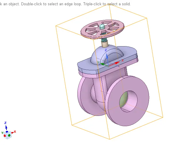
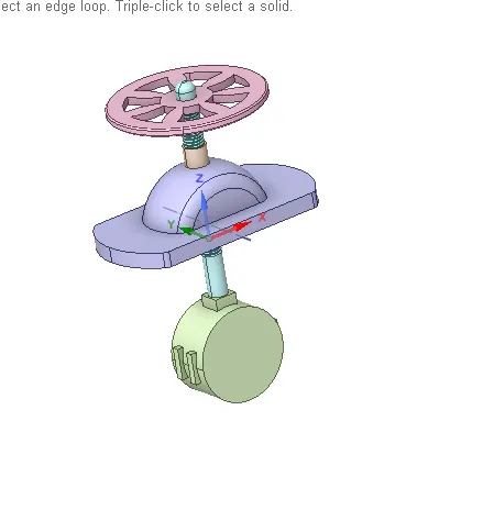
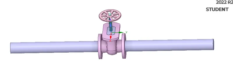
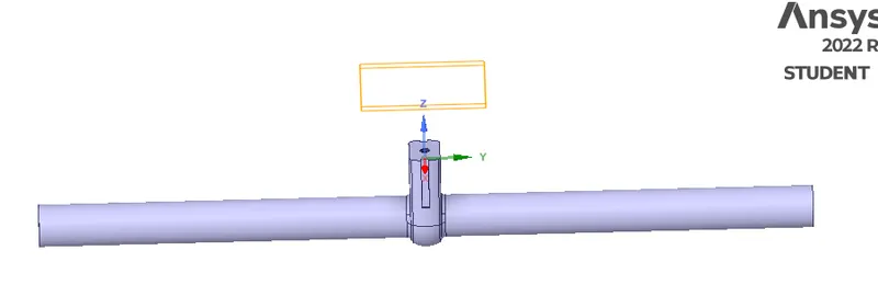
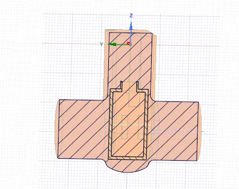
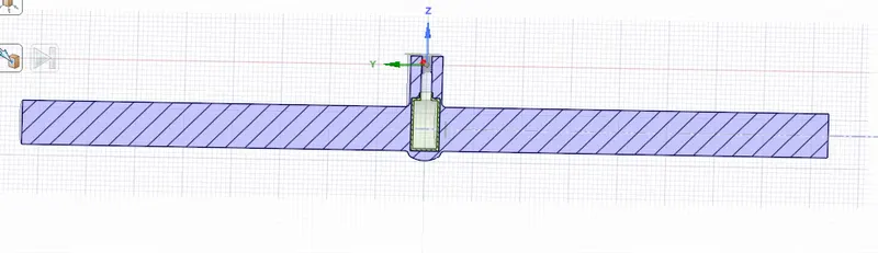
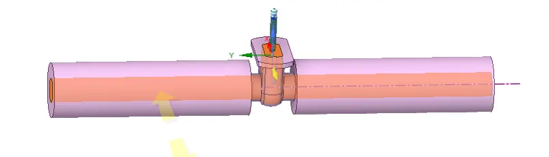
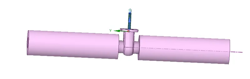
Geometry:
Meshing:

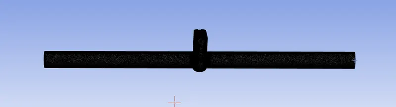
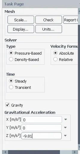
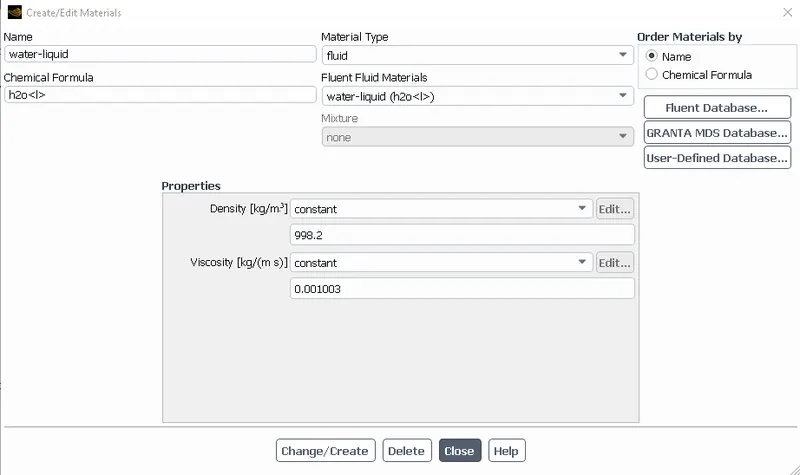
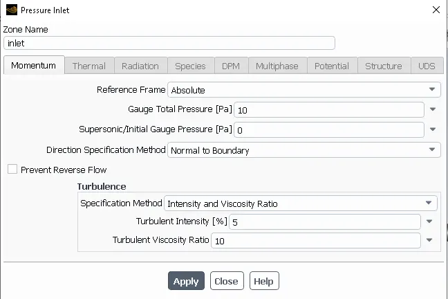
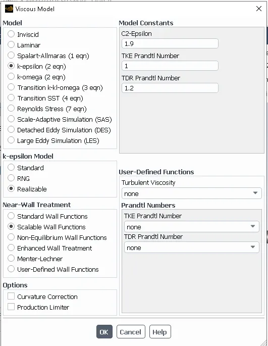
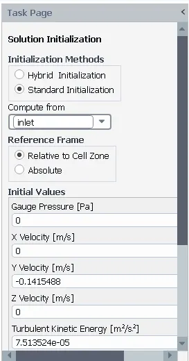
Setup and Solution:

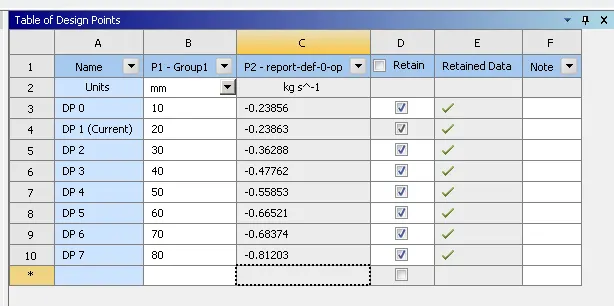
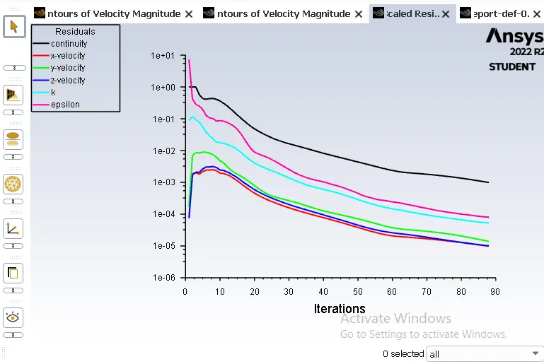
10 mm Lift:
Residual Plot:
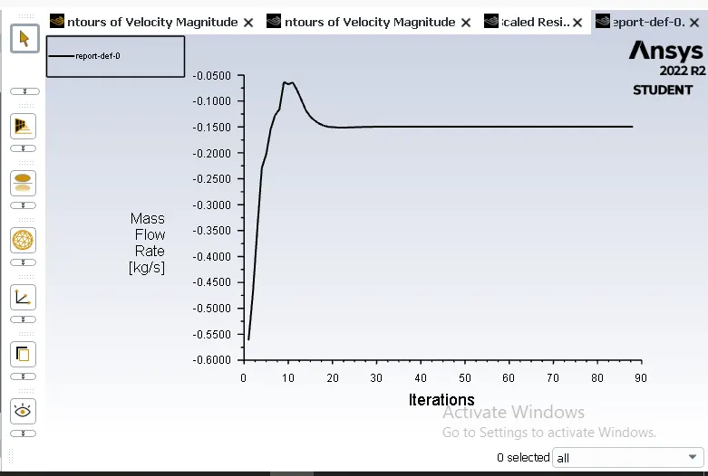
Mass flow rate:
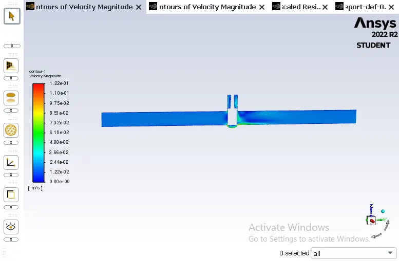
Velocity Contour Plot:
20 mm lift:
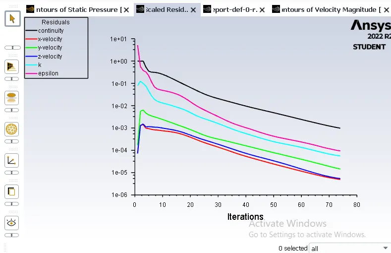
Residual plot:
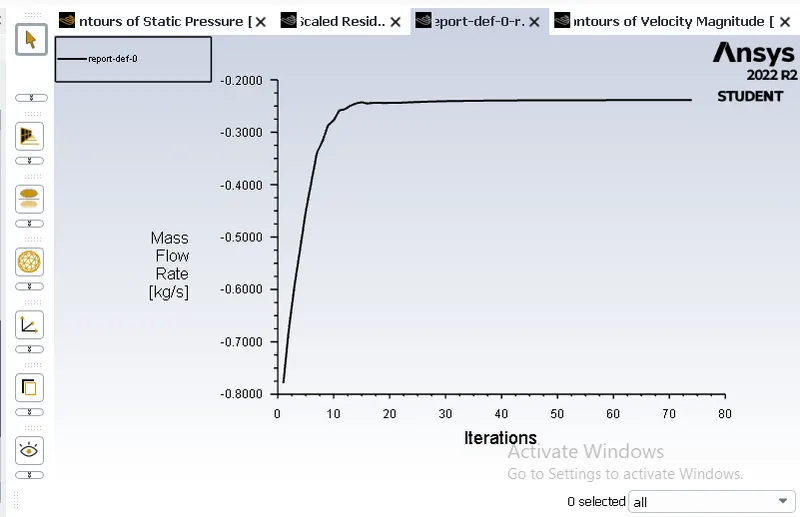
Mass flow rate:
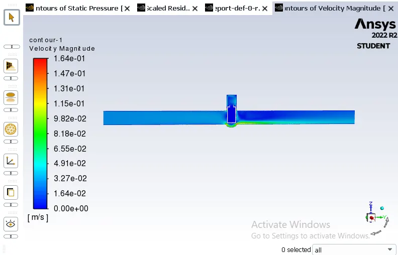
Velocity plot:
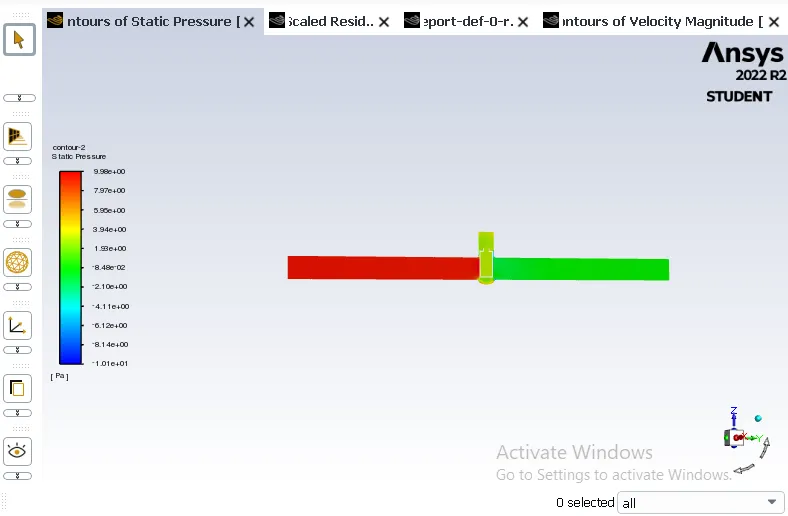
Pressure plot:
30 mm lift:
Residual plot:
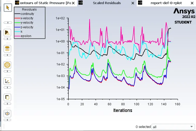
Mass flow rate:
Velocity plot:
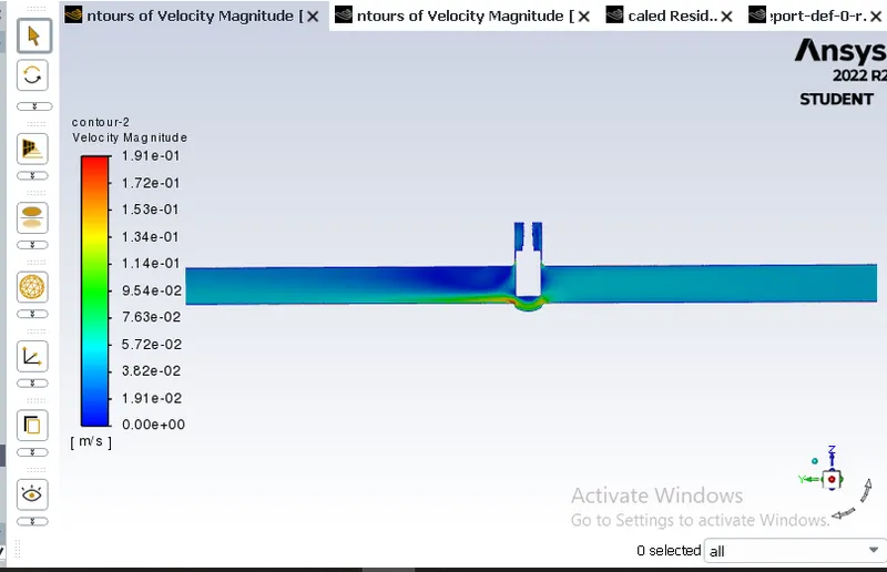
Pressure plot:
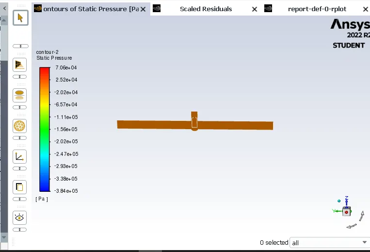
40 mm lift:
Residual plot:
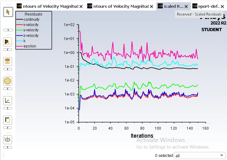
Mass flow rate:
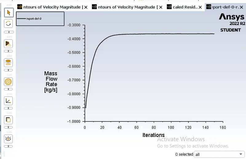
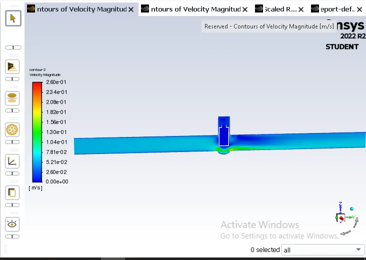
Velocity plot:
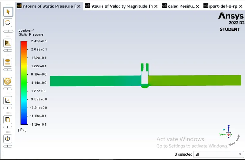
Pressure plot:
50 mm lift:
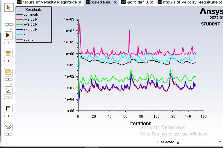
Residual plot:
Mass flow rate:
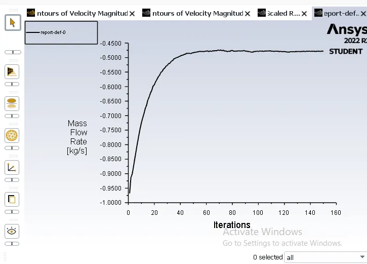
Velocity plot:
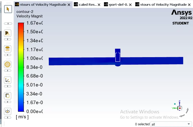
Pressure plot:
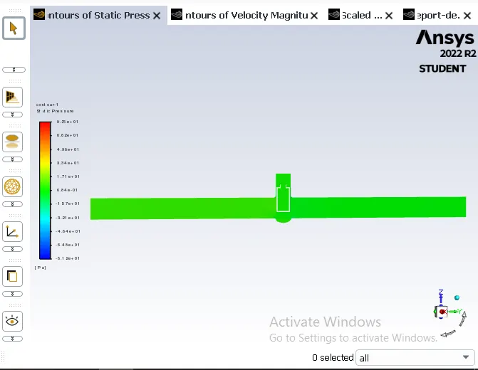
60 mm lift:
Residual plot:
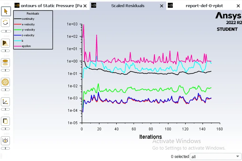
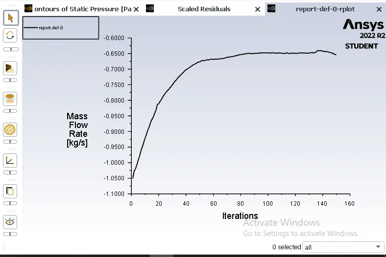
Mass flow rate:
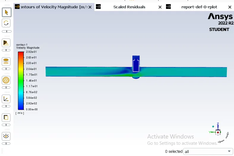
Velocity plot:
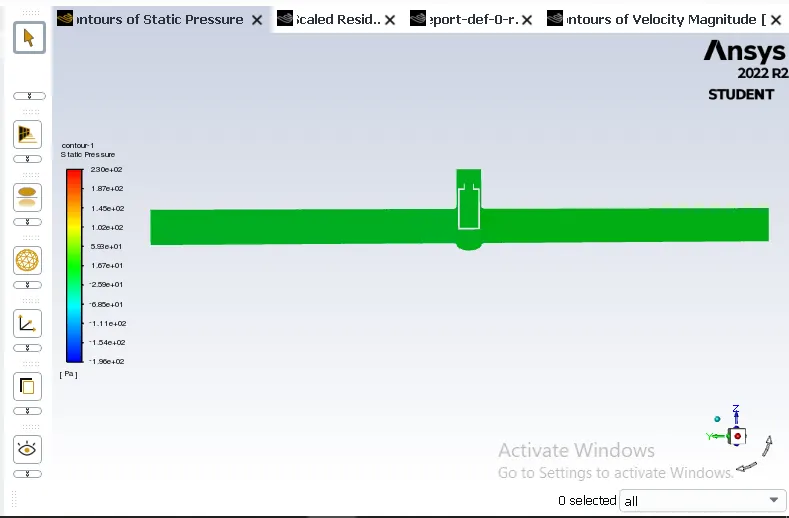
Pressure plot:
70 mm lift:
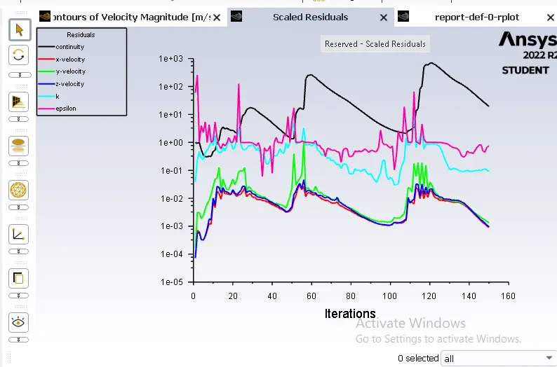
Residual plot:
Mass flow rate:
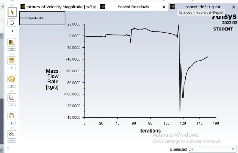
Velocity plot:
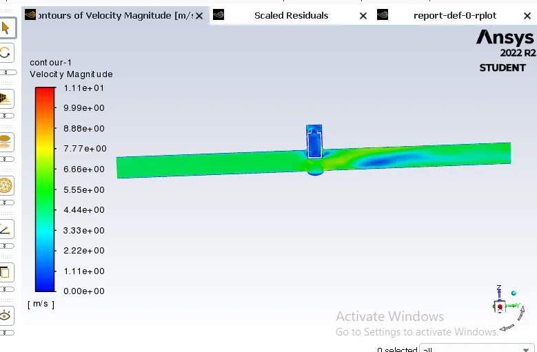
Pressure plot:
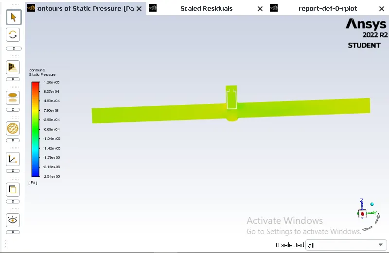
80 mm lift:
Residual plot:
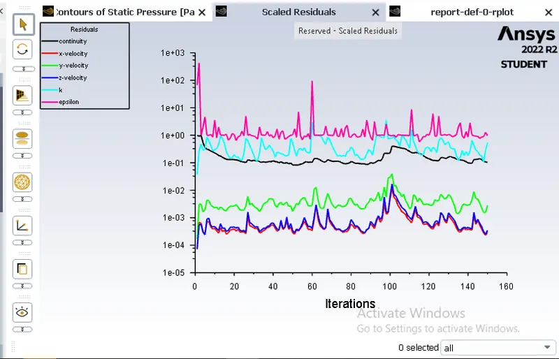
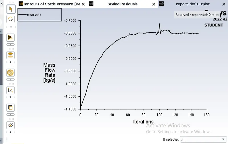
Mass flow rate:
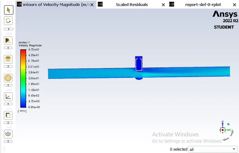
Velocity plot:
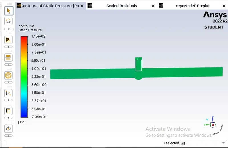
Pressure plot:
2. Calculate the flow coefficient and flow factor for each opening.
Mass flow rate:
m = rho*Q
m = mass flow rate
rho = density of water
Q = rate of flow
Flow coefficient:
C = Q*(S/P)1/2
C = flow coefficient
S = specific gravity of water is 1
P = pressure drop
Flow factor:
K = Q*(S/P)1/2
K = flow factor
The relationship between flow coefficent and flow factor
C = 1.16*K
K = 0.82*C
| Cases | Mass flow rate | Lift | Flow coefficient | Flow factor |
| 1 | 0.14804 | 10mm | 0.16853 | 0.13819 |
| 2 | 0.23863 | 20mm | 0.27166 | 0.22276 |
| 3 | 0.36288 | 30mm | 0.41308 | 0.33875 |
| 4 | 0.47762 | 40mm | 0.54373 | 0.44586 |
| 5 | 0.55853 | 50mm | 0.63584 | 0.52139 |
| 6 | 0.66521 | 60mm | 0.75728 | 0.62097 |
| 7 | 0.68374 | 70mm | 0.77838 | 0.63827 |
| 8 | 0.81203 | 80mm | 0.92443 | 0.75803 |
Conclusion:
1. We successfully created mass flow rate plot, pressure plot and velocity plot respectively.
2. Study of different cases help us to understand how gate valve mechanism work under various cases.
3. We concluded that in first case the lift is very small so inlet velocity and pressure is very small
4. Pressure at inlet is very high as flow passes through valve pressure graudually decreases.
5. There is gradual increase in Mass flow rate,Flow coefficient and Flow factor as the lift increases from 10mm to 80mm.
Reference:
https://www.theprocesspiping.com/introduction-to-gate-valve/