Week 2 - Flow over a Cylinder.
Aim: Simulate the flow over a cylinder and explain the phenomenon of Karman vortex street.
PART-I
- Simulate the flow with the steady and unsteady case and calculate the Strouhal Number for Re= 100.
PART-II
- Calculate the coefficient of drag and lift over a cylinder by setting the Reynolds number to 10,100,1000,10000 & 100000. (Run with steady solver)
- Discuss the effect of Reynolds number on the coefficient of drag. [ Results should be validated with any standard literature and error should be within 5 %]
Expected results:-
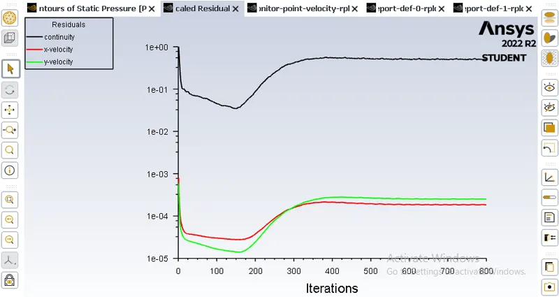
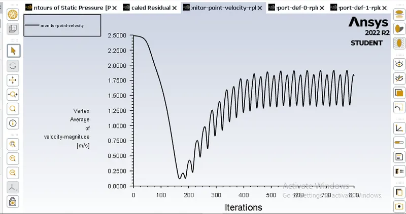
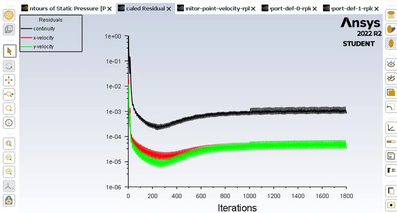
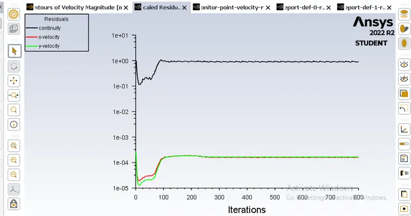
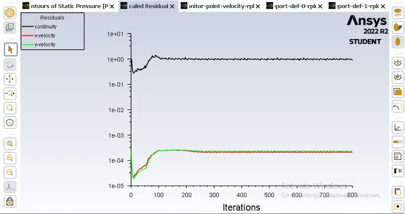
- In both approaches, show that the flow has converged. That is, what quantities or plots need to be looked at to determine that the flow has converged?
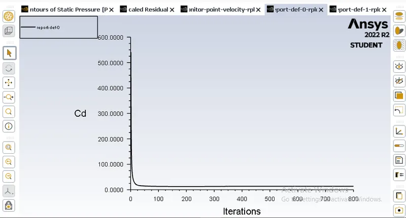
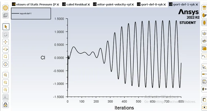
- Plots of the coefficient of drag and lift.
- Plots to show vortex shedding behind the cylinder.
- Mention the referred material (Reference Paper or Fluid Mechanics Textbook) at the end of the challenge submission page.
Procedure:
1. Step one open spaceclaim and create cylinder.
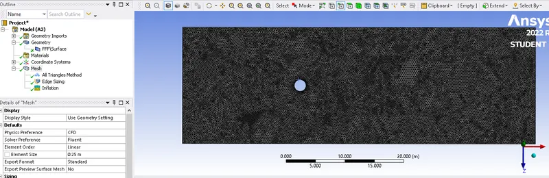
2. Mesh the cylinder and provide name selection to cylinder.
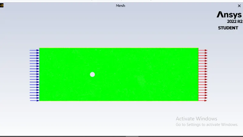
3. Last step open the model in setup and provide all the boundary condition and set the iteration to achieve the require results.
What is Reynold Number?
he Reynolds number represents the ratio of inertial forces to viscous forces and is a convenient parameter for predicting if a flow condition will be laminar or turbulent. It is defined as a characteristic length multiplied by a characteristic velocity and divided by the kinematic viscosity.
Key Facts
- Osborn Reynolds discovered that the flow regime depends mainly on the ratio of the inertia forces to viscous forces in the fluid.
- When the viscous forces are dominant (slow flow, low Re), they are sufficient to keep all the fluid particles in line, then the flow is laminar.
- When the inertial forces dominate over the viscous forces (when the fluid flows faster and Re is larger), the flow is turbulent.
- It is defined as:in which V is the mean flow velocity, D is a characteristic linear dimension, ρ fluid density, μ dynamic viscosity, and ν kinematic viscosity.
- The Reynolds number can be used to compare a real situation (e.g.,, airflow around an airfoil and water flow in a pipe) with a small-scale model.
Drag Coefficient

 |
= | drag coefficient |
 |
= | Drag Force |
 |
= | density |
 |
= | flow speed of the object relative to the fluid |
 |
= | reference area |
Lift Coefficient
The lift coefficient is defined as: CL = L/qS , where L is the lift force, S the area of the wing and q = (rU2/2) is the dynamic pressure with r the air density and U the airspeed.
What is Strouhal Number?
he Strouhal Number is a dimensionless value useful for analyzing oscillating unsteady fluid flow dynamics problems.
The Strouhal Number can be expressed as
St = ω l / v
where
St = Strouhal Number
ω = oscillation frequency
l = characteristic length
v = flow velocity
The Strouhal Number can be important when analyzing unsteady, oscillating flow problems. The Strouhal Number represents a measure of the ratio of the inertial forces due to the unsteadiness of the flow or local acceleration to the inertial forces due to changes in velocity from one point to an other in the flow field.
PART-I
- Simulate the flow with the steady and unsteady case and calculate the Strouhal Number for Re= 100.
Re = 100
Kinematic Viscosity = 0.05 m^2/s
Diameter = 2 m
V = 100*0.05/2 = 2.5 m/s
Steady State
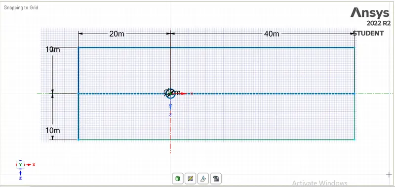
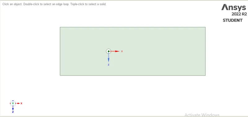
Mesh Element size is 0.25 m
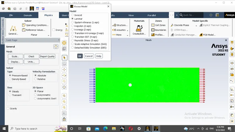
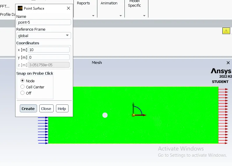
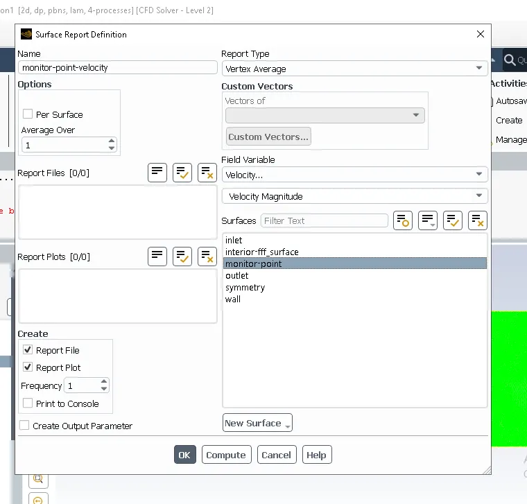
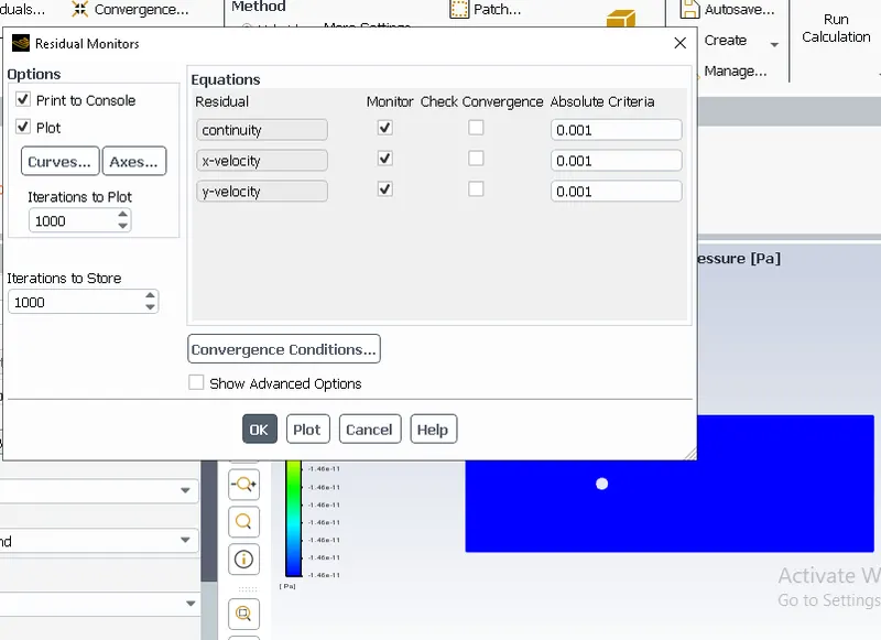
Residual Plot:
Monitor Point:
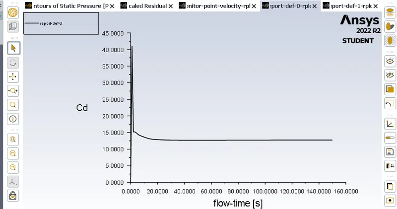
Drag Coefficient:
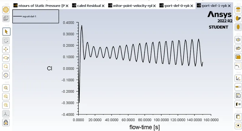
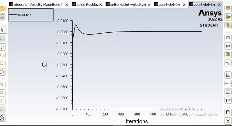
Lift Coefficient:
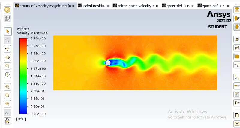
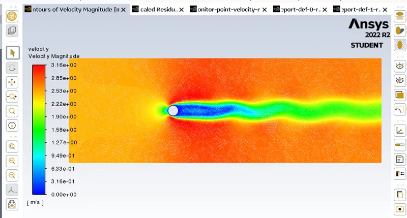
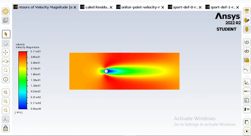
Velocity Contour:
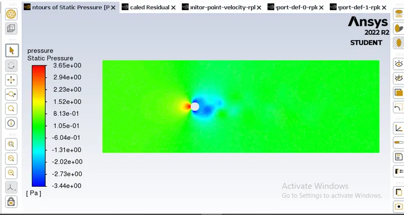
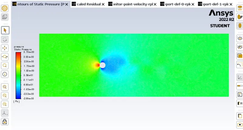
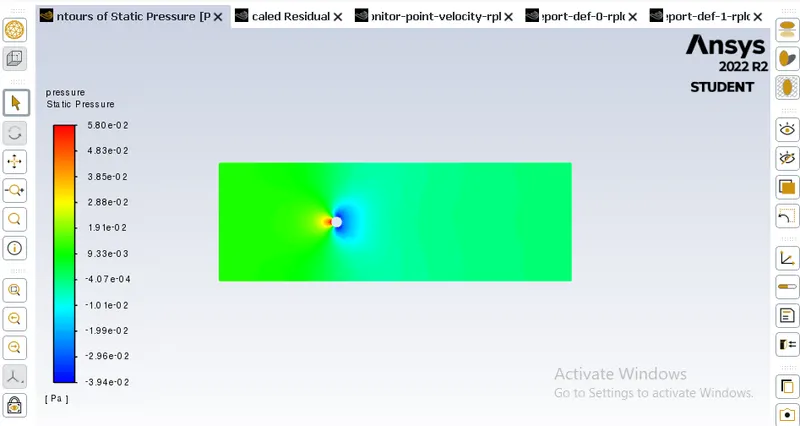
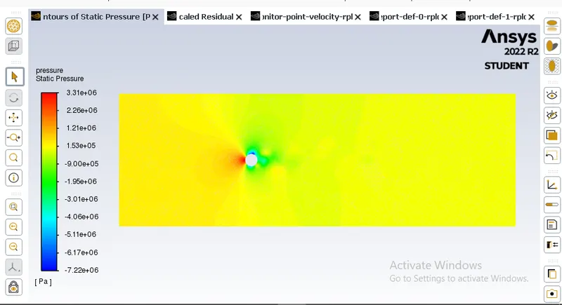
Pressure Contour:
Unsteady State:
Residual Plot:
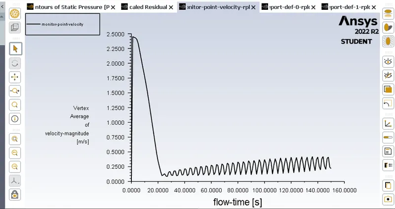
Monitor Point:
Drag Coefficient:
Lift Coefficient:
Velocity Contour:
Pressure Contour:
Strouhal Number:
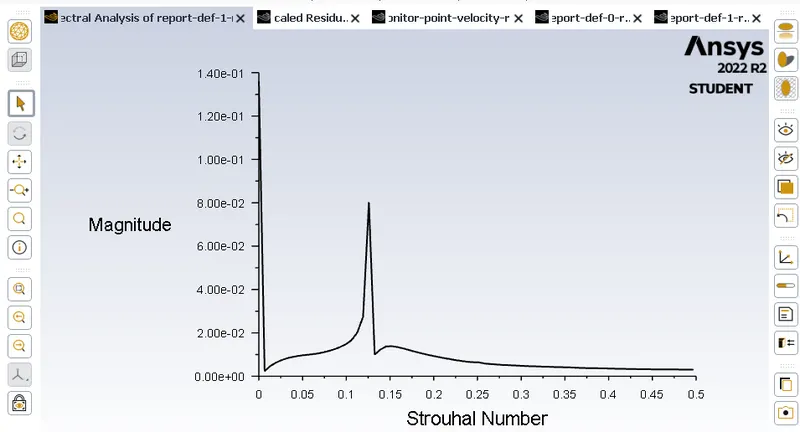
Strouhal Number = 0.14
PART-II
- Calculate the coefficient of drag and lift over a cylinder by setting the Reynolds number to 10,100,1000,10000 & 100000. (Run with steady solver)
- Discuss the effect of Reynolds number on the coefficient of drag. [ Results should be validated with any standard literature and error should be within 5 %]
Case 2.1 Re = 10
Velocity = 0.25 m/s
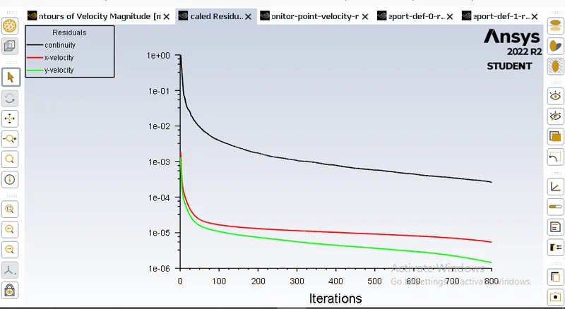
Residual Plot:
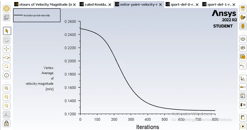
Monitor Point:
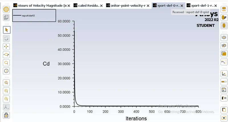
Drag Coefficient:
Lift Coefficient:
Velocity Contour:
Pressure Contour:
Case 2.2 Re = 100
Velocity = 2.5 m/s
Residual Plot:
Monitor Point:
Drag Coefficient:
Lift Coefficient:
Velocity Contour:
Pressure Contour:
Case 2.3 Re = 1000
Velocity = 25 m/s
Residual Plot:
Monitor Point:
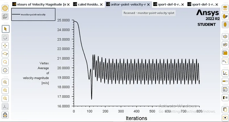
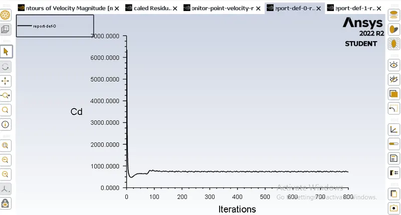
Drag Coefficient:
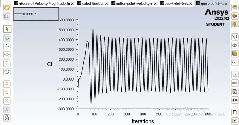
Lift Coefficient:
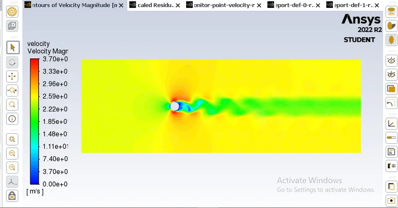
Velocity Contour:
Pressure Contour:
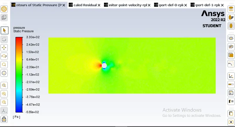
Case 2.4 Re = 10000
Velocity = 250 m/s
Residual Plot:
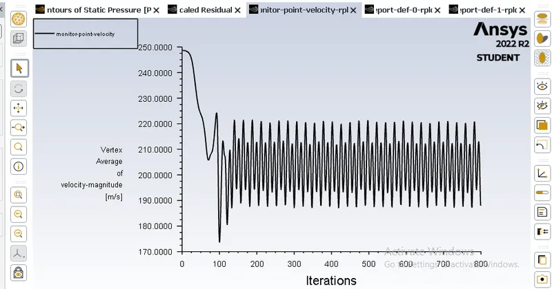
Monitor Point:
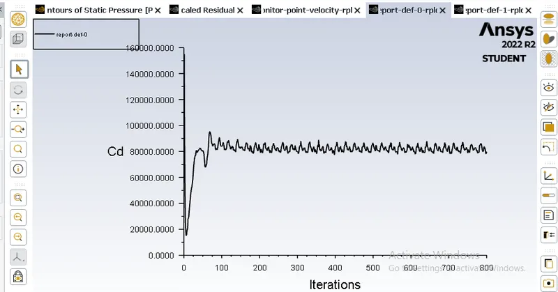
Drag Coefficient:
Lift Coefficient:
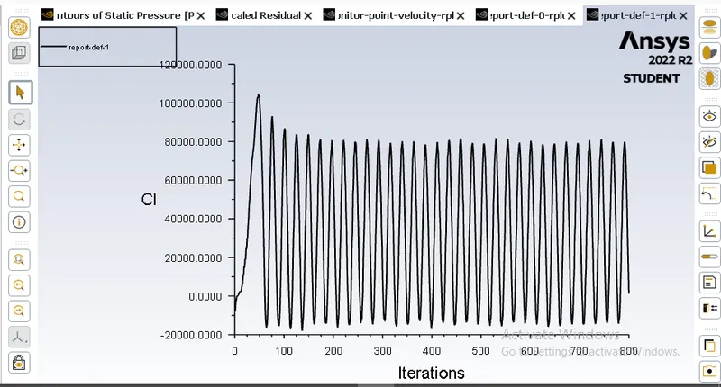
Velocity Contour:
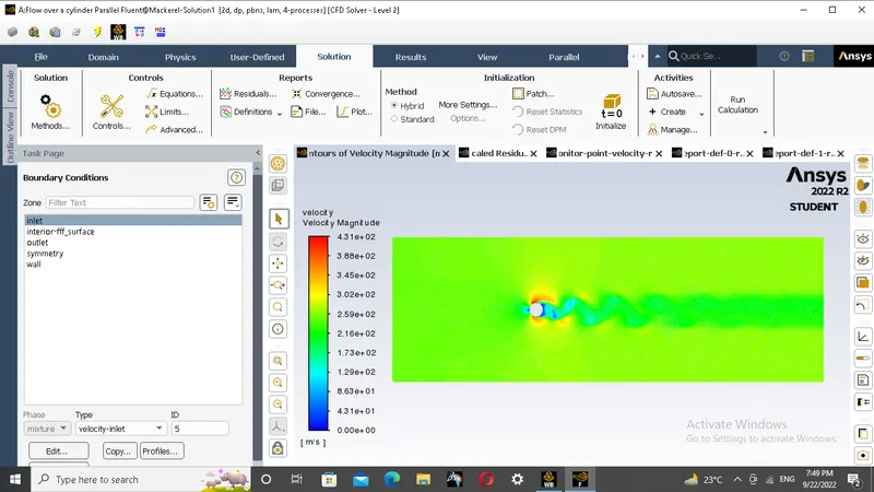
Pressure Contour:
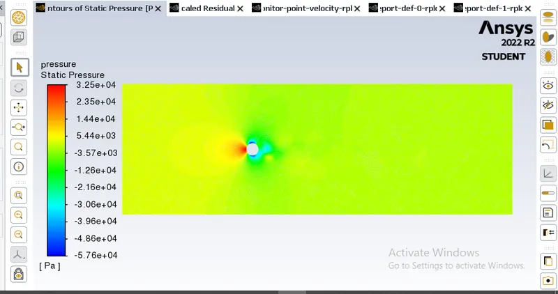
Case 2.5 Re = 10000
Velocity = 2500 m/s
Residual Plot:
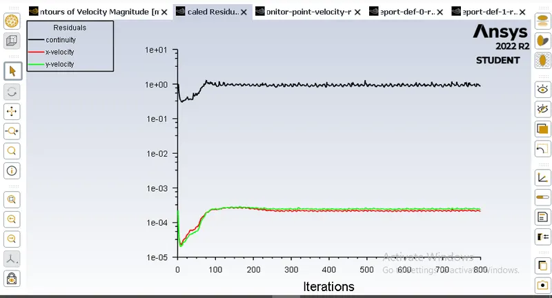
Monitor Point:
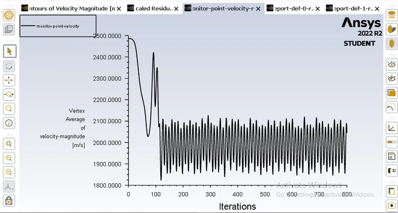
Drag Coefficient:
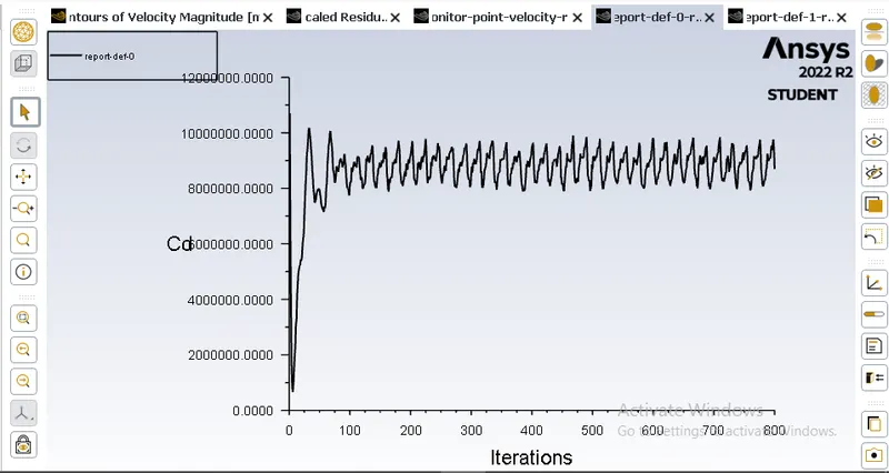
Lift Coefficient:
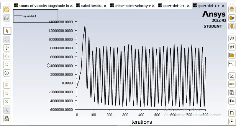
Velocity Contour:
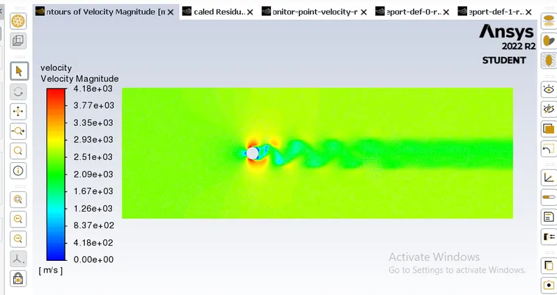
Pressure Contour:
Conclusion:
1. We successfully created the cylinder in Spacclaim
2. We successfully mesh the component and provide require output.
3. We successfully plot the velocity contour,presssure contour,Residual plot,Velocity-Monitor plot,Drag coefficient plot and lastly the Lift coefficient plot.
References:
https://www.sciencedirect.com/science/article/pii/S0307904X08000243