Week 8 Multi cell Battery Pack
How weakest cell limits the usable capacity of the battery pack? What is the solution?
What is cell imbalance?
Common multiple cell configurations for Li-Ion cells in battery packs consist of three or four cells in series, with one or more cells in parallel. This combination gives both the voltage and power necessary for Portable Computer, medical, test and industrial applications. While these configurations are common today, they may not be as efficient as they could be. The reason for this is that any capacity mismatch between cells in a series connection of cells results in a reduction of overall pack capacity.
There are two kinds of mismatch in the pack, State-of-Charge (SOC) and capacity/energy (C/E) mismatch. Each problem limits the pack capacity (mAh) to the capacity of the weakest cell. It is important to recognize that the cell mismatch results more from limitations in process control and inspection than from variations inherent in the Lithium Ion chemistry. As such, these types of cell to cell variation more likely occur in Li-Ion prismatic cells, due to more extreme mechanical stresses, and in Li-Ion Polymer, due to the newer processes involved.
Causes of cell Imbalance
The individual cells in a battery pack naturally have somewhat different capacities, and so, over the course of charge and discharge cycles, may be at a different state of charge (SOC).
Variations in capacity are due to the following reasons:
- Manufacturing variances
- Assembly variances (e.g., cells from one production run mixed with others)
- Cell aging
- Impurities
- Environmental exposure (e.g., some cells may be subject to additional heat from nearby sources like motors, electronics, etc.)
Soft shorts are the primary cause of cell imbalance in some cells. Due to tiny imperfections in cell construction the cell can have very high resistance shorts on the order of 40,000 ohms or more. The self discharge rate due to this higher resistance is on the order of 0.1 milliamperes or 3% per month.
Another source of pack cell imbalance occurs when cells remain on the shelf for long periods of time prior to assembly. This is compounded if cells from different manufacturing lots are mixed within a pack. Even after assembly, imbalances can develop over time within the pack, if cells within a pack vary significantly ” especially if the pack remains “on the shelf” for a significant period.
Effects of weak Cell during charging/discharging
Battery chargers detect full charge by checking whether the voltage of the entire string of cells has reached the voltage-regulation point, individual cell voltages can vary as long as they do not exceed the limits for overvoltage (OV) protection. However, weak cells—i.e., cells with lower capacity or higher internal impedance—tend to exhibit higher voltage than the rest of the series cells at full charge termination. These cells are weakened further by continuous overcharge cycles. The higher voltage of weak cells at charge completion causes accelerated capacity degradation.
On the other hand, in discharge, the weak cells tend to have lower voltage than the other cells, due to either higher internal resistance or the faster rate of discharge that results from their smaller capacity. This means that if any of the weak cells hits the cell under voltage-protection limit while the pack voltage is still sufficient to power the system, the full capacity of the battery will not be used.
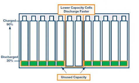
Figure 1: Parallel connected cells with weak cell
It can be seen that even though there may be quite a bit of capacity left in several batteries, the weak batteries limit the run time of the system. A battery mismatch of 5% results in 5% of the capacity being unused. With large batteries, this can be an excessive amount of energy left unused. This becomes critical in remote systems and systems that are difficult to access. As a result, there is a portion of energy that cannot be used, which results in an increase in the number of battery charge and discharge cycles. Furthermore, this unused energy reduces the lifetime of the battery and leads to higher costs associated with more frequent battery replacement.
Effect of Faulty cell in series and parallel connection
Figure 2 illustrates a battery pack in which “cell 3” produces only 2.8V instead of the full nominal 3.6V. With depressed operating voltage, this battery reaches the end-of-discharge point sooner than a normal pack. The voltage collapses and the device turns off with a “Low Battery” message.

Figure 2: Series connection with a faulty cell.
Faulty cell 3 lowers the voltage and cuts the equipment off prematurely.
A cell that develops high resistance or opens is less critical in a parallel circuit than in a series configuration, but a failing cell will reduce the total load capability. It’s like an engine only firing on three cylinders instead of on all four. An electrical short, on the other hand, is more serious as the faulty cell drains energy from the other cells, causing a fire hazard. Most so-called electrical shorts are mild and manifest themselves as elevated self-discharge.
A total short can occur through reverse polarization or dendrite growth. Large packs often include a fuse that disconnects the failing cell from the parallel circuit if it were to short. Figure 3 illustrates a parallel configuration with one faulty cell.
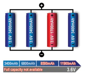
Figure 3: Parallel/connection with one faulty cell.
A weak cell will not affect the voltage but provide a low runtime due to reduced capacity. A shorted cell could cause excessive heat and become a fire hazard. On larger packs a fuse prevents high current by isolating the cell.
Figure 4 shows how to simulate a battery pack consisting of multiple series-connected cells in an efficient manner. It also shows how a fault can be introduced into one of the cells to see the impact on battery performance and cell temperatures. For efficiency, identical series-connected cells are not just simply modeled by connecting cell models in series. Instead a single cell is used, and the terminal voltage scaled up by the number of cells. The fault is represented by changing the parameters for the Cell 10 Fault subsystem, reducing both capacity and open-circuit voltage, and increasing the resistance values.
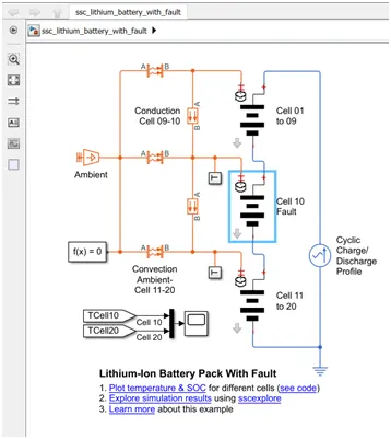
Figure 4: MATLAB simulation of faulty cell
Figure 4 shows the MATLAB simulation model of faulty cell. Cell 10 is configured as faulty cell and it’s performance has been compared with other cells in figure 5. We can see that the temperature of faulty cell is higher than that of other cells. From SOC plot, the faulty cell charges lower than that of other cells and discharges to a lower rate than other cells.
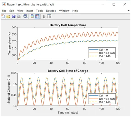
Figure 5: Plot of Cell temperature and SOC of different battery cells
Cell Balancing to Improve Battery Performance
Cell balancing is a technique that improves battery life by maximizing the capacity of a battery pack with multiple cells in series, ensuring that all of its energy is available for use. A cell balancer or regulator is functionality in a battery management system that performs cell balancing often found in lithium-ion battery packs electric vehicles and ESS applications. The fundamental solution of cell balancing equalizes the voltage and SOC among the cells when they are at full charge. Cell balancing is usually categorized into two types—passive and active. The passive cell-balancing method, also known as “resistor bleeding balancing,” is simple and straightforward: Discharge the cells that need balancing through a dissipative bypass route. This bypass can be either integrated or external to the IC. Such an approach is favorable in low-cost system applications.
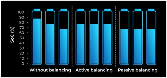
Figure 6: Comparison of cells without balancing, Active and Passive balancing
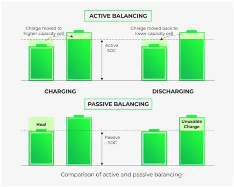
Figure 7: Comparison of Active and Passive Cell Balancing
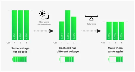
Figure 8 : Passive cell balancing
A passive system potentially burns off excess energy from the high cells through a resistive element until the charge matches the lower energy cells in the pack. If you have cells packed in series and you notice that some of the cells have higher energy than the other lower energy cells, you can balance the cells in burning energy of the top cells simply by attaching a resistor to the cells which releases the energy into heat thereby equalizing the cell energy of the battery pack.
Initially, you burn off the excess energy until you have balanced cells. Passive cell balancing allows all cells to appear to have the same capacity. There are two different categories of passive cell balancing method: fixed shunting resistor and switching shunting resistor. A fixed shunting resistor circuit is usually connected to the fixed shunting to prevent it from being overcharged. With the help of the resistors, the passive balancing circuit can control the limit value of each cell voltage without damaging the cells. Energy consumed by these resistors for balancing a battery may result in thermal losses in the BMS. This, therefore, proves the fixed shunting resistor method to be an inefficient cell equalizing circuit.
The switch shunting resistor cell balancing circuit is currently the most common method in cell equalizing. This method has a continuous mode and a sensing mode, where the continuous mode all switches are controlled to be turned on or off at the same time and in the sensing mode, a real-time voltage sensor is required for each cell. This cell balancing circuit consumes high energy through a balancing resistor. This cell balancing circuit is suitable for a battery system that requires a low current when it is charged or discharged.
Advantages of Passive Cell Balancing:
- You should never have to balance a pack that is working perfectly.
- A cell cannot waste energy that it does not have. As soon as the energy bank is full, that is only when the cell has enough energy to balance.
- It allows all cells to have the same SoC.
- It provides a fairly low-cost method for balancing the cells.
- It can correct for long-term mismatch in self-discharge current from cell to cell.
Disadvantages of Passive Cell Balancing:
- Poor thermal management.
- They do not balance during the full SoC. They only balance through the top of each cell at around 95%. This is because if you have different cell capacities, you are forced to burn off the excess energy.
- Its energy transmission efficiency is usually low. Electrical energy is dissipated as heat in the resistors and the circuit also accounts for switching losses. In other words, it results in a high amount of energy loss.
- It does not improve the run-time of a battery-powered system.
Active Cell Balancing
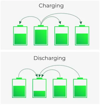
Figure 9: Active cell balancing
An active cell balancer generally transfers energy from one cell to another. That is from high voltage/ high SoC to a cell with a lower SoC. The purpose of an active balancer is that if you have a pack of cells with lower capacity, you can extend the life or the SoC that you have on the pack by moving energy from one cell in the pack with more energy than the other cell.
Instead of wasting all that energy as heat, an active cell balancer efficiently balances cells with tiny converter circuits that pass energy from the highest voltage cells to the lowest voltage cells. There are two different categories of active cell balancing methods: charge shuttling and energy converters. Charge shuttling is used to actively transport charges from one cell to another to achieve equal cell voltage. Energy converters use transformers and inductors to move energy among the cells of a battery pack.
Other active cell balancing circuits are typically based on capacitors, inductors or transformers, and power electronics interface. These entail:
Based on capacitors
- Single capacitors – this method is simple because it uses a single capacitor regardless of the number of cells connected in the battery. However, this method requires a large number of switches and intelligent control of the switches.
- Multiple capacitors – this method with multiple capacitors connected to each battery transfers unequal cell energy by multiple capacitors. It does not require a voltage sensor or closed-loop control.
Based on inductors or transformers
- Single/ multiple inductors – a cell balancing circuit with a single inductor has a small volume and low cost while multiple inductors have fast balancing speed and decent cell balancing efficiency.
- Single transformer – this method has a fast balancing speed with low magnetic losses.
- Multiple transformers – this cell balancer has a fast equalizing speed. However, it requires an expensive and complex circuit that prevents the transformer from being flooded.
Based on Power Electronics Interface
- Flyback/ forward converter – the energy of a high voltage cell is stored in the transformer. This cell balancer has high reliability.
- Full-bridge converter – this cell balancer has fast equalization speed and high efficiency.
Active balancers are capable of pushing a lot of current from one cell to another.
Read more about ‘Active cell balancing for maximum battery pack performance’, here.
Advantages of Active Cell Balancing:
- It improves capacity usage. It performs great when you have different cell capacities in a series.
- It increases energy efficiency. It saves energy instead of burning the excess energy in a cell by transferring the excess energy to a lower energy cell.
- Lifetime extension. It improves the life expectancy of a cell.
- Fast balancing.
Disadvantages of Active Cell Balancing:
- When you transfer energy from one cell to another, approximately 10-20% of the energy is lost.
- The charge could be transferred only from higher cell to lower cell.
- Although an active cell balancer has high energy efficiency, its control algorithm may be complex and its production cost is expensive because each cell should be connected with an additional power electronics interface.