Week-7 Challenge: DC Motor Control
- Run MATLAB demo ‘Speed control of a DC motor using BJT H-bridge’. Modify the model such that armature current doesn’t shoot up when motor changes direction from forward to reverse.
Solution
The MATLAB demo model of ‘Speed control of a DC motor using BJT H-bridge’ is as shown below.
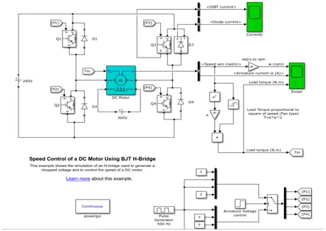
Figure 1: DC Motor using H-bridge
The simulink model for DC motor control with H-bridge is shown in figure1. This consists of 4 switches and 4 diodes. The basic operation of H bridge circuit is given below.
Basic H-Bridge Circuit
H Bridge is a simple electronic circuit which enables us to apply voltage to load in either direction. It is commonly used in robotics application to control DC Motors. By using H Bridge we can run DC Motor in clockwise or anticlockwise directions.
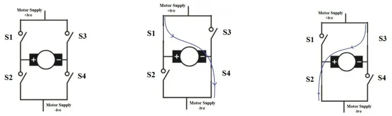
Fig 2.(a):Basic H-bridge (b): Motor runs in clockwise (c): Motor runs in anticlockwise
The control signals are given through a pulse generator. For first 0.5sec, pulse will be given to P1 and P4 to make Q1 and Q4 ‘ON’. The motor will run clockwise during this time and speed is shown positive in the output waveform shown below.
After 0.5sec, pulse will be given to P2 and P3 to make Q2 and Q3 ‘ON’. The motor will run anticlockwise and the speed is shown negative.
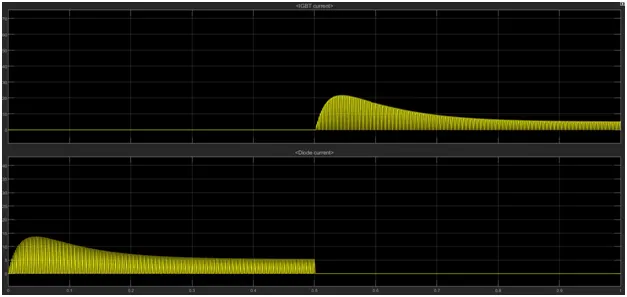
Figure 3: Switch transition in H-bridge
We can see the switches on and off state during 0.5sec in figure 3.
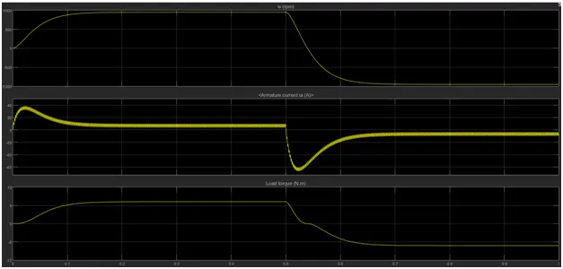
Figure 4: Output Waveforms of motor control using H-bridge
Figure 4 shows the speed, armature current and load torque of motor. We can see that when motor changes its direction from positive to negative when supply voltage reverses. During this transition, motor armature current shoots up and goes to a peak value of -66A. We can also see that the ripple in the armature current is more than 6A in figure 5.

Figure 5: Peak Armature Current during negative transition
To reduce the shootout current of armature, we can add a series resistor to the armature.
We know that for DC motor, Torque T = (V*Kϕ)/Ra – (ω/Ra)* (Kϕ)^2
Torque, (ω/Ra)* (Kϕ)^2 = (V*Kϕ)/Ra – T
Speed, ω = V/Kϕ – (T* Ra) / (Kϕ)^2
By adding a series resistor, the speed will decrease as per the above relation.
We have also added a smoothing reactance to reduce the armature current ripple. The RL load connected in series with the armature is shown below.
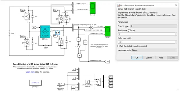
Figure 6: Modified Simulink model for reduced armature shoot up current
In figure 6, a series resistor of 5ohms has been added to reduce armature current and an inductance of 100mH has been added to reduce armature ripple.
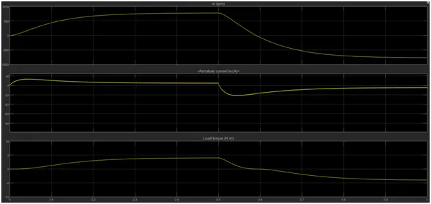
Figure 7: Output waveforms for modified model
In figure 7, we can see that armature current is -20A which is far less than the -66A condition without series resistor. The ripple in armature current has also reduced to 1A. But the speed also reduced due to increase in armature current. To maintain the same speed as before, we can increase the duty cycle as given below.
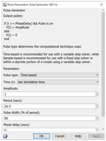
Figure 8: Increasing pulse width to increase speed
In order to compensate for the reduced speed, duty cycle has been increased to 80% as shown above. As the duty cycle increases, Armature voltage increases and speed increases.
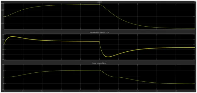
Figure 9: Output waveforms with increased duty cycle
In figure 9, we can see that the speed has been increased due to increase in duty cycle and the shoot up current of armature is is -25A which is a slight increase than -20A in Figure 7.
Conclusion
The armature current shoot up and ripples has been reduced by adding a series resistance and smoothing inductance to the armature. To compensate the speed reduction by increasing the armature resistance, duty cycle has been increased. Thus reduced armature shoot up current and ripples with same speed has been achieved.
2.Refer to help section of ‘The Four-Quadrant Chopper DC Drive (DC7) block’. Compare it with H-bridge model.
Solution
The four quadrant Chopper DC drive simulink model is shown below.
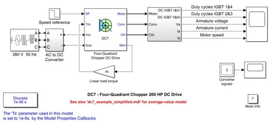
Figure 10: Simulink model of the Four Quadrant Chopper DC Drive.
DC7 Drive
In this DC7 Drive, a 200HP separately excited DC motor has been used. The field windings are excited separately with a 150V source. The armature voltage and current has been controlled by 4 quadrant chopper.
The converter is fed by a 515 V DC bus obtained by rectification of a 380 V AC 50 Hz voltage source. In order to limit the DC bus voltage during dynamic braking mode, a braking chopper has been added between the diode rectifier and the DC7 block.
The first regulator is a speed regulator, followed by a current regulator. The speed regulator outputs the armature current reference (in p.u.) used by the current controller in order to obtain the electromagnetic torque needed to reach the desired speed. The speed reference change rate follows acceleration and deceleration ramps in order to avoid sudden reference changes that could cause armature over-current and destabilize the system. The current regulator controls the armature current by computing the appropriate duty ratios of the 5 kHz pulses of the four IGBT devices (Pulse Width Modulation). For proper system behaviour, the instantaneous pulse values of IGBT devices 1 and 4 are opposite to those of IGBT devices 2 and 3. This generates the average armature voltage needed to obtain the desired armature current. In order to limit the amplitude of the current oscillations, a smoothing inductance is placed in series with the armature circuit.
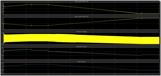
Figure 11: Output Waveforms of four quadrant DC chopper drive
Comparison between H-Bride model and 4 Quadrant Chopper DC drive
|
4 Quadrant Chopper DC drive |
H-Bridge DC drive |
|
DC7 model contains a speed reference block and current regulator to control armature shoot up current |
No current control methods are used. So armature current shoots up drastically. |
|
Smoothing inductance is added to reduce armature current ripples. |
No smoothing inductance added. Armature current has high ripples. |
|
Four quadrant operation possible |
Only two quadrant operation is possible. |
|
Forward motoring and braking, Reverse motoring and braking are possible |
Forward and reverse motoring operations are only possible |
|
Regenerative braking operation possible |
Braking is not possible |
|
Can be implemented for EV applications |
Cannot be used for EV applications as regenerative braking is not possible |
|
High Efficiency due to regenerative braking and better current control |
Efficiency is less as armature heating loss occurs due to peak current during transition. |
3.Make a suitable EV model using DC7 block and make result report.
Solution
EV model using DC7 drive is as shown in figure 12. The AC source and the inverter has been replaced by Li-Ion battery. The reference speed is given through a drive cycle source and the torque is provided through a block which will calculate torque required by the vehicle for the corresponding speed.
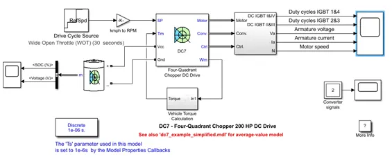
Figure 12: Modified EV model using DC7 block
For modeling EV vehicle, calculate the torque required for the vehicle to oppose rolling resistance and aerodynamic drag.
Rolling Resistance = m*g*Crr =1200*9.81*0.01
Aerodynamic drag resistance = 0.5 *delta* Cd * Af * V^2 = 0.5 * 1.225 * 0.35 * 3.2 * (0.38*ω)^2
These two calculations have been implemented through function blocks. We have taken wheel diameter as 15inches. Multiplying the force by wheel diameter with sum of these forces, will give the torque as shown below.
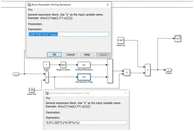
Figure 13: EV Torque model Implementation
By modelling the torque block as above, the torque response will be same as the EV. The input to this block is the speed in rad/s and output Torue will be again fed back to DC7 block.
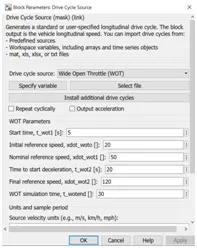
Figure 14: Drive cycle source settings
The step response source has been replaced with WOT source as shown above. This is given in terms of kmph. To convert it into RPM, we have to use the below equation.
r = k/(d × 0.001885)
Where,
k = Kilometer Per Hour(km/hr)
d = Wheel Diameter(cm)
r = Revolution Per Minute(RPM)
r= k /(38.1*0.001885)
So the gain block has been provided for this factor.
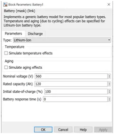
Figure 15: Battery Parameters
The Li-Ion battery parameters are given above in figure 15.
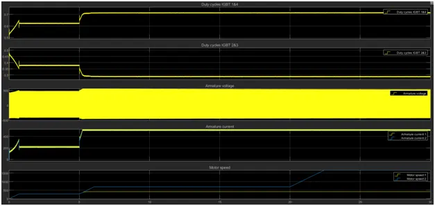
Figure 16: Output waveforms of EV response to WOT cycle
The output waveforms of EV are given above. We can see that the motor is following the given input speed.
Conclusion
Using the DC7 drive, the EV has been simulated and the WOT response plotted. The four quadrant chopper DC drive found suitable for EV applications.