Week-6 Challenge: EV Drivetrain
1.Which types of power converter circuits are employed in electric and hybrid electric vehicle?
An Electric Vehicle is a vehicle that uses a combination of different energy sources, Fuel Cells (FCs), Batteries and Supercapacitors (SCs) to power an electric drive system as shown in Figure 1.
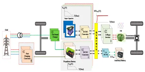
Figure 1: Electric Vehicle Drive power train
In EV the main energy source is assisted by one or more energy storage devices. Thereby the system cost, mass, and volume can be decreased, and a significant better performance can be obtained. Two often used energy storage devices are batteries and SCS. They can be connected to the fuel cell stack in many ways. A simple configuration is to directly connect two devices in parallel, (FC/battery, FC/SC, or battery/SC). However, in this way the power drawn from each device cannot be controlled, but is passively determined by the impedance of the devices. The impedance depends on many parameters, e.g. temperature, state-of-charge, health, and point of operation. Each device might therefore be operated at an inappropriate condition, e.g. health and efficiency. The voltage characteristics also have to match perfectly of the two devices, and only a fraction of the range of operation of the devices can be utilized, e.g. in a fuel cell battery configuration the fuel cell must provide almost the same power all the time due to the fixed voltage of the battery, and in a battery/supercapacitor configuration only a fraction of the energy exchange capability of the supercapacitor can be used. This is again due to the nearly constant voltage of the battery. By introducing DC/DC converters one can chose the voltage variation of the devices and the power of each device can be controlled.
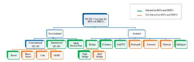
Figure 2: Classification of DC-DC Converter Topologies
Non-Isolated DC-DC Converters for BEVs and PHEVs
Non-isolated DC-DC converters are frequently used in medium and high-power vehicular Applications. The commonly used DC-DC converters for BEV and PHEV applications are given below.
- Boost DC-DC converters
- Interleaved Boost DC-DC converters
- Multistage converters
Conventional boost DC-DC converters and interleaved Boost DC-DC converters are commonly used for BEV and PHEV powertrains due to their simple architecture, cost-e_ectiveness and accessible control strategy. These two converters are used at low and medium DC link voltage applications. For example, a boost DC-DC converter is employed where low DC voltage gain is required (<4%). For a low level of DC voltage gain, there are four types of converter available: boost converter, buck-boost converter, C´uk converter and SEPIC converter. Among all these the boost converter topology is selected for BEVs and PHEVs because only a positive voltage gain (>1) is required for motor action; whereas buck-boost converters, C´ uk converters, and SEPIC converters can be used for both voltage step-up and step-down operation. Moreover, C´ uk and SEPIC are current-voltage-current converters, which are only suitable for energy storage systems (ESSs), whereas the inputs can be a battery and/or a SC in vehicular applications. The high inrush output current and use of a large volume filter capacitor make the buck-boost topology inconvenient in automotive applications. Again, when a high gain DC Bus voltage is required (>4%), the interleaved 4-Phase interleaved boost converter is employed. Interleaved Boost Converters (IBCs) can step up the voltage more than a 4:1 ratio with minimum input current ripples and output voltage ripples, and this makes IBCs a preferable choice among non-isolated converter topology.
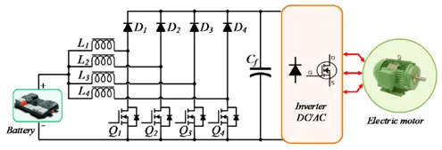
Figure 3: Interleaved boost converter
Isolated DC-DC Converters for BEVs and PHEVs
IsolatedDC-DC converters are often used in low and medium-power vehicular applications. Among them, the full-bridge isolated DC-DC converter is the most popular topology for BEV and PHEV powertrains. Five different types of isolated DC-DC converter topologies are frequently used:
- Full-bridge converter
- Z-source converter
- Multiport Converter
- Sinusoidal Amplitude High Voltage bus converter
Isolated DC-DC converter operation has three primary stages DC/AC/DC. The intermediate AC stage surges up the input voltage to a higher level using a high-frequency transformer (HFT). The HFT provides galvanic isolation and high voltage gain which are significant issues in BEVs and PHEVs.
Full-bridge is the most suitable converter topology among these five types because it reduces voltage and current stresses over switches and diodes which is absent in all other isolated topologies. Moreover, full-bridge design architecture is simple and it improves overall system efficiency with minimal cost.
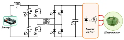
Figure 4: Full bridge DC-DC Converter
Z-source converters as single boosting stage (DC/AC) become popular in BEV and PHEV powertrains due to their smooth starting operation, low voltage stress on switching gates and low current ripples , but they have a limited boosting capability due to the limited voltage gain during the zero vectors.
A Sinusoidal Amplitude High Voltage bus converter (SAHVC) suppresses the EMI from the circuity which results in low dv/dt and di/dt rates in switch on mode and switch o_ mode. Due to this feature, the SAHVC can function properly at high switching frequencies with minimal switching losses while maintaining a high-power density. Moreover, isolated-MPC is the best-suited candidate in BEVs and PHEVs because it reduces input current ripples and output voltage ripples, minimizes the size of passive components, improves efficiency and having high power handling capability.
Multiport converters will combine multiple sources with transformer isolation and provide the advantage of single source connectivity. Each source is connected using interleaving technique which will limit output voltage and output current ripples.
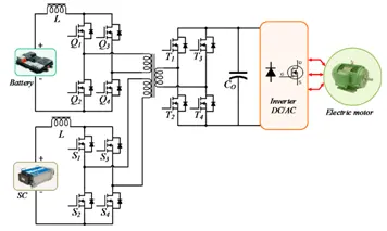
Figure 5: Multiport Converter
Inverter
The inverter is a bi-directional converter, that accepts the high voltage from the traction battery and converts it typically in the three phase AC voltage suitable for the traction. During the deceleration (regenerative breaking period) the motor absorbs the torque and provide the AC voltage to the inverter. The inverter controls the amount of the energy generated by the motor and consequently the intensity of the braking. The harvested energy is applied back to the HV battery as a charge. The regenerative breaking improves significantly the vehicle efficiency and in turn the distance the vehicle can travel on a given battery charge.
The most common topology of the EV & HEV inverter is the three-phase bridge, Fig.6. It uses IGBTs with anti-parallel diodes as a switch.
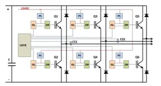
Figure 6: Standard 3-ph bridge Inverter
Hence the commonly used DC- DC converter and Inverter topologies have been discussed.
2.An Electric Vehicle's power train with 72V battery pack in shown in the diagram below. The duty ratio for acceleration operation is 'd1' and for the braking operation the duty ratio is 'd2'.
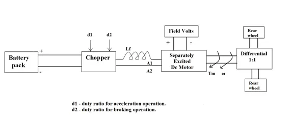
The other parameters of the electric vehicle is given below,
Motor and Controller Parameters:
Rated Armature voltage= 72 V, Rated armature current= 400 A, Ra= 0.5Ω, KΦ= 0.7 Volt second, Chopper Switching frequency= 400 Hz
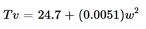
The vehicle speed-torque characteristics are given by the below equation
What is EV steady state speed if duty cycle is 70%?
Solution
In the above circuit, the battery is connected to a chopper. So the supply voltage to the motor will be the output of chopper. Let’s discuss the principle of chopper to find the voltage supplied to the motor.
Chopper
A chopper is basically a dc to dc converter whose main function is to create adjustable dc voltage from fixed dc voltage sources through the use of semiconductors.
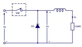
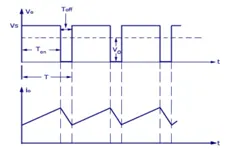
Figure 7: Step down chopper circuit and waveforms
Average output voltage of chopper is given by:
V0 = Vs (Ton/T)
Where Ton = On time of switch
T = Ton + Toff = Total time period
In the above circuit,
Battery voltage/ Input voltage to the chopper = 72V
Duty cycle of Chopper = 70% = 0.7
The output voltage = 0.7 * 72 = 50.4V
Torque Equation of motor
Torque, T = (V*Kϕ)/Ra – (ω/Ra)* (Kϕ)^2 ----------------- (1)
Where, V= Supply voltage, Ra = Armature resistance
ω = Speed of motor in rad/s
Kϕ = Speed constant of motor
Substituting in eq.(1), V= 50.4V, Ra = 0.5Ohms, Kϕ = 0.7
T = (50.4 * 0.7)/0.5 – (0.7)^2 * (ω/0.5)
T = 70.56 – 0.98 ω ------------------ (2)
T = 24.7 + 0.0051 ω^2 ------------------ (3)
Equating (2) and (3),
70.56 – 0.98 ω = 24.7 + 0.0051 ω^2
By rearranging,
0.0051ω^2 + 0.98 ω – 45.86 = 0 ------------- (4)
Solving (4), we get ω = 38.91 , -231.0.7
Since the drive is in motoring mode we can take speed as positive. ω = 38.91 rad/s
So the EV steady state speed = 38.91 rad/s
3.Refer to the blog on below topic:
Induction Versus DC brushless motors by Wally Rippel, Tesla
Explain in brief about author’s perspective.
Solution
There is no one best choice in the case of engines. According to application and performance, the choice of engines will also vary. The same is true for Electric drives. AC Induction drives and DC brushless drives are the two main types of drives in EV field. Both has its own advantages and disadvantages in case of performance, cost, development etc. The author gives some key points to understand the challenges in choosing drives in EV.
Both DC brushless and induction drives use motors having similar stators. Both drives use 3-phase modulating inverters. The only differences are the rotors and the inverter controls. And with digital controllers, the only control differences are with control code.
|
Induction motors |
DC Brushless motors |
|
Speed sensor is enough |
Needs an absolute position sensor |
|
Rotor heat has to be controlled by appropriate cooling. |
Less heat generated at rotor. So less cooling required. |
|
Best power factor is 85% |
Can operate at unity power factor |
|
Average efficiency is better |
Peak point energy efficiency is high and average efficiency less due to magnetic losses |
|
No need of permanent magnets. |
Require permanent magnets in the rotor |
|
No permanent magnets in rotor |
Costly due to Permanent magnets |
|
Require complex control algorithms. |
Require an inverter to operate |
|
Losses do not necessarily grow as machine size. |
Loss increases as machine size increases |
|
Development of drive is costly. No recurring costs. |
Recurring costs are high due to magnetic losses. |
|
Achieving stability is difficult |
Easier than induction motor |
The Author's points about the Induction motor and Brushless DC motor are listed in the above table. He also summarizes that both induction motor and DC motor has to be developed side by side for EV applications since each has got its advantages and disadvantages.