Mechanical design of battery pack
AIM
To Prepare a detailed battery pack drawing along with its enclosure using ANR26650M1-B cylindrical cells of pack capacity 18 kWh
Objective
To create a battery pack using ANR26650M1-B cylidrical cells by calculating number of cells, battery voltage and capacity. The complete battery pack installation including battery holders, Thermal management, BMS and size calculation of the enclosure has to be done.
Battery pack Calculation[2]
The battery pack voltage, no.of cells and size of battery pack has to be calculated to design the enclosure. For that, the specifications of the cell has been extracted in table 1.
Datasheet of ANR26650M1-B [1]
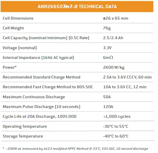
Table 1: Technical data of ANR26650 M1-B
The number of battery cells connected in series Ncs in a string is calculated by dividing the nominal battery pack voltage Ubp [V] to the voltage of each battery cell Ubc [V]. The number of strings must be an integer. Therefore, the result of the calculation is rounded to the higher integer.
Ncs = Ubp / Ubc --------------------------- (1)
The energy content of a string Ebs [Wh] is equal with the product between the number of battery cells connected in series Ncs and the energy of a battery cell Ebc [Wh].
Ebs=Ncs * Ebc --------------------------- (2)
The total number of strings of the battery pack Nsb is calculated by dividing the battery pack total energy Ebp [Wh] to the energy content of a string Ebs [Wh]. The number of strings must be an integer. Therefore, the result of the calculation is rounded to the higher integer.
Nsb = Ebp / Ebs ---------------------------- (3)
We can now recalculate the battery pack total energy Ebp [Wh] as the product between number of strings Nsb and the energy content of each string Ebs [Wh].
Ebp = Nsb * Ebs --------------------------- (4)
The battery pack capacity Cbp [Ah] is calculated as the product between the number of strings Nsb and the capacity of the battery cell Cbc [Ah].
Cbp = Nsb * Cbc ---------------------------- (5)
The total number of cells of the battery pack Ncb is calculated as the product between the number of strings Nsb and the number of cells in a string Ncs.
Ncb = Nsb * Ncs --------------------------- (6)
The battery pack mass (cells only) mbp [kg] is the product between the total number of cells Ncb and the mass of each battery cell mbc [kg].
mbp=Ncb * mbc ---------------------------- (7)
The volume of the battery pack (cells only) Vbp [m3] is the product between the total number of cells Ncb and the mass of each battery cell Vcc(pc) [m3]. This volume is only used to estimate the final volume of the battery pack, since it does not take into account the auxiliary components/systems of the battery.
Vbp=Ncb * Vcc(pc) -------------------------- (8)
The volume can be also calculated function of number of strings and number of cells in a string. This calculation method is more appropriate for cylindrical cell, since the volume occupied by a cylindrical cell must take into account the air gap between cells.
Selection of battery voltage [3]
- Today’s electric vehicles (EV) use a high system voltage due to the reduction of the appearing current. This results in a much more complex electrical system (high-voltage side: IT topology) compared to that of a conventional car with an internal combustion engine. This can be explained by the need to ensure the safety of the passengers, the maintenance staff or the rescue personnel, in the case of an accident.
- Current battery systems for hybrid and battery electric vehicles typically have operating voltages of 200–800 Volts [3].
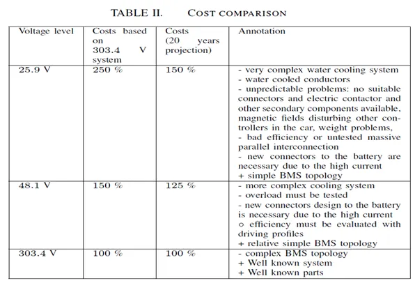
Table 2: Comparison of battery pack at different voltage levels
From the above table, we can see that higher voltage battery pack are more advantageous than the lower voltage systems.
So in our system, we are taking battery voltage as 303.6V
From equation (1),
Battery cells connected in series, Ncs = 303.6 / 3.3 = 92
From (2)
Battery cell energy, Ebc = 2.5 * 3.3 = 8.25wh
From (3)
Energy content of a string, Ebs = Ncs * Ebc = 92* 8.25 = 759 Wh
From (4)
Number of strings of the battery pack, Nsb = Ebp / Ebs = 18000 / 759 = 24
From (5)
Battery pack capacity Cbp [Ah] = Nsb * Cbc = 24 * 2.5 = 60
From (6)
Numbers of cells of the battery pack Ncb = Ncs * Nsb = 92 * 24 = 2208
From (7)
Battery pack mass (cells only) mbp [kg] = 2208 * 0.076 = 167.8 kg
Battery Module and Pack Assembly – Production Steps and Challenges
Battery module and pack assembly brings up a number of challenges: About 500 single parts have to be assembled in one battery system. There are e.g. 300 screw connections and 200–300 welding points to be set. The assembly of tubing and cover plates can only be achieved manually. A special requirement is workplace safety: the more cells are assembled, the higher the voltages that occur. Automation is possible for most of the process steps, but careful consideration if it pays off is needed. Investment into automation also depends on regional specialties. Battery production is still in an evolutionary phase (at least for high-power applications), i.e. requirements for automated production rapidly change.
Although highly desirable for cost-effective production, a lot of production steps today still require manual handling, as indicated above. This is partly due to the precision required, partly a lack of measurement technology, and partly an economical issue.
The important components of battery pack are given below.
- Battery Holders[4]
There are different types of battery holders available in the market. Figure 1 shows the connector which has the following advantages.
- needs no spot welding and soldering
- Resists vibration and loosening
- Safer
- Fully customizable
- Easily serviceable

Figure 1: Battery holder which needs no spot welding
Disadvantages
- Battery pack density will be less.
- Costly
Hexagonal caps
These battery holders are designed to maximize the packing density of an 18650 battery pack. That means you can fit more cells into less space, while still maintaining air gaps between cells.
The battery holders come as a group of 3. Those can then be snapped together to create larger packs. This means you can have a pack as small as 3 cells or as large as thousands of cells. Simply continue snapping together the holders to reach larger pack sizes.
The connectors are very lightweight, at just 1.75 grams per 3 cell holder. For a 52 cell battery, for example, the connectors add just 60 grams or 0.13 lbs of weight while still holding all of the cells absolutely rigid.
Please note: unlike the previous connectors, these hexagonal caps are only for holding the cells. They do not include any electrical connections. That means you need to join your cells using another method (spot welding, soldering, etc.)
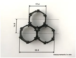
Figure 2: Hexagonal connectors
- Thermal Management of EV batteries [5]
The performance of Lithium-Ion battery cells is greatly impacted by their temperature, they suffer from the Goldilocks effect, they do not perform well when too cold or too hot, which can lead to permanent and extreme damage of the cells or accelerated degradation. So in addition to cooling, heating of the cells may also be required at lower ambient temperatures to prevent damage during fast charging when the cells are too cold.; this is because the internal resistance of the cells rises when they are cold. Most lithium battery cells cannot be fast charged when they are less than 5°C and cannot be charged at all when they are below 0 °C. Lithium cells also begin to degrade quickly when their temperature is above 45°C.
There are 3 common battery thermal management methods used today:
1. Convection to air either passively or forced.
2. Cooling by flooding the battery with a dielectric oil which is then pumped out to a heat exchanger system.
3. Cooling by circulation of water based coolant through cooling passages within the battery structure.
- BMS for Battery packs
- Simple passive regulators achieve balancing across batteries or cells by bypassing charging current when the cell's voltage reaches a certain level. The cell voltage is a poor indicator of the cell's SOC (and for certain Lithium chemistries such as LiFePO4 it is no indicator at all), thus, making cell voltages equal using passive regulators does not balance SOC, which is the goal of a BMS. Therefore, such devices, while certainly beneficial, have severe limitations in their effectiveness.
- Active regulators intelligently turning on and off a load when appropriate, again to achieve balancing. If only the cell voltage is used as a parameter to enable the active regulators, the same constraints noted above for passive regulators apply.
- A complete BMS also reports the state of the battery to a display, and protects the battery.
BMS topologies fall in 3 categories:
- Centralized: a single controller is connected to the battery cells through a multitude of wires
- Distributed: a BMS board is installed at each cell, with just a single communication cable between the battery and a controller
- Modular: a few controllers, each handing a certain number of cells, with communication between the controllers
Centralized BMSs are most economical, least expandable, and are plagued by a multitude of wires. Distributed BMSs are the most expensive, simplest to install, and offer the cleanest assembly. Modular BMSs offer a compromise of the features and problems of the other two topologies.
The requirements for a BMS in mobile applications (such as electric vehicles) and stationary applications (like stand-by UPSs in a server room) are quite different, especially from the space and weight constraint requirements, so the hardware and software implementations must be tailored to the specific use. In the case of electric or hybrid vehicles, the BMS is only a subsystem and cannot work as a standalone device. It must communicate with at least a charger (or charging infrastructure), a load, thermal management and emergency shutdown subsystems. Therefore, in a good vehicle design the BMS is tightly integrated with those subsystems. Some small mobile applications (such as medical equipment carts, motorized wheelchairs, scooters, and fork lifts) often have external charging hardware, however the on-board BMS must still have tight design integration with the external charger.
Steps for making Battery Pack
Step 1:
Since our battrey pack is of high density, we have to choose hexagonal connectors and join them as shown in figure3.

Figure 3: Joining Hexagonal connectors
Step 2:
Insert the cells inside these connectors with positive and negative poles kept alternatively in adjascent rows.
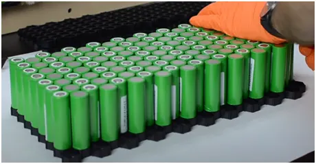
Figure 4: Inserting cells inside the connectors
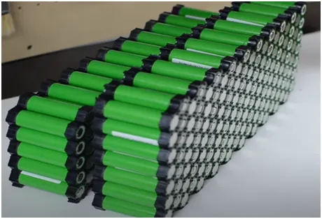
Figure 5: Insert connectors on top and bottom side
Step 3:
Spot weld with nickel strips to make series connection between the cells as shown in figure 6.
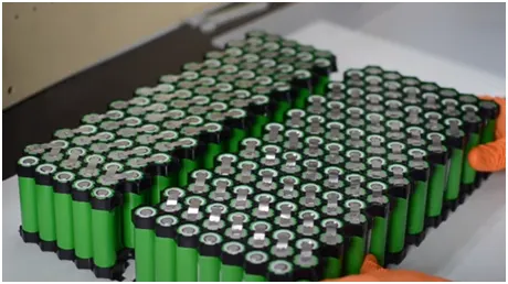
Figure 6: Make series connection of batteries
After making series connections, connect the strings in parallel. And complete the connection as per figure 7 and 8.
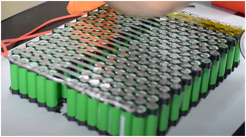
Figure 7: Connect the strings in parallel
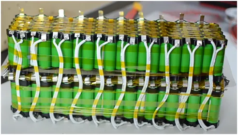
Figure 8: Complete the connection using wires
Step 4:
Install BMS for the battery pack as shown in figure 9.
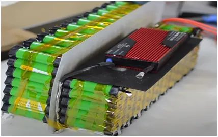
Figure 9: Install BMS for the battrey pack
Step 5:
Install cooling structures for air cooling/ liquid cooling as shown in figure 10,11, 12
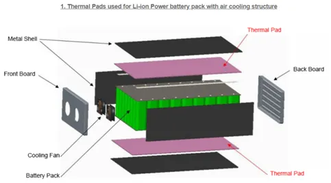
Figure 10: Install thermal pads for battery pack with air cooling
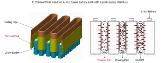
Figure 11: Battery pack with liquid cooling
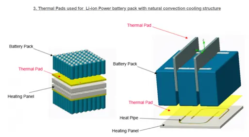
Figure 12: Battery pack with convection cooling structure
Step 6:
Install the battery pack inside the enclosure as shown in figure 13.
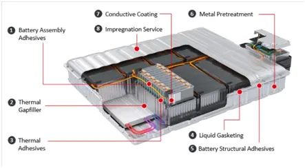
Figure 13: Installing battery pck inside the enclosure
Calculation of Enclosure size
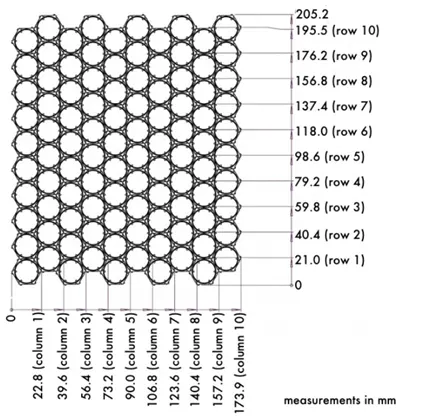
From the above figure, we can understand that
Approximate length of battery pack excluding BMS, Thermal pad and other accessories can be calculated as, L = Connector length for 100cells * No.of cells/200 = 205.2* 2208 /200 = 2265.408 mm
Width of battery pack, W = Connector width for 100cells * No.of cells/200 = 173.9 * 2208 /200 = 1919.856 mm
From the above calculation, approximate size of battery pack will be 2.3*2 m
Enclosure for battery packs
There are different types of enclosures available for the battery pack. A few are explained below. The main features required for EV battery enclosures are:
- Light weight
- Shock and Vibration proof
- Fire protection
- Prevent Electro magnetic radiation
- Low cost
- Aluminum sheet battery enclosure
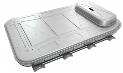
Figure 15: Aluminium Enclosure
Aluminum's inherent properties — corrosion resistance and recyclability — make the metal attractive in electric-vehicle manufacturing. The enclosure regulates thermal conductivity by helping to cool and heat the battery cells.
Using aluminum to enclose a lithium ion battery pack in an EV can reduce weight by about 50 percent.
Weight savings translates into longer driving range, a major challenge for the competitiveness of electric vehicles.
The lightweight aluminum translates into a lower cost per weight at mass-production volumes.
- Glass Fiber based enclosures
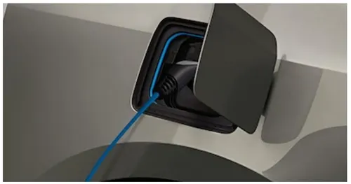
Figure 16: Glass Fiber based enclosures
Materials made of composites are suited for battery enclosures for different reasons: Besides their light weight, which enhances the electric vehicle’s range, fiber-reinforced plastics offer high stiffness. In addition, they meet high requirements for water and gas tightness and feature excellent fire protection properties. Composite materials can also help to achieve improved structural stiffness of the underbody, e.g. to protect against penetration, as well as an optimized thermal management. Carbon fibers are ideal for especially stressed structures or load-bearing elements, such as the underbody panels and side frames. For components subjected to less stress, such as battery box covers, glass fibers or a fiber mix may suffice.
- Light weight Composite solutions[6]
TRB has been working on a project to develop safe and robust battery enclosures. This collaborative project has focused on the production of battery boxes and modules for a new fleet of electric buses that are being rolled out in the USA, supporting the drive towards more sustainable transportation. Advantages
- Lightweight and robust battery enclosures
- Carbon fibre composite
- Additional layers to prevent electrical conductivity and electromagnetic radiation
- Partnership contributing to all stages of product development
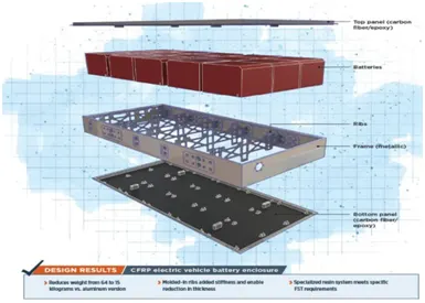
Figure 17: Light weight composite structure enclosures
Conclusion
A battery pack has been designed using ANR26650M1-B cylidrical cells by calculating number of cells, battery voltage and capacity. The steps of battery pack installation has been explained in detail. The different types of battery holders, thermal management and latest enclosures has been explained. The required size of battery pack also has been calculated.
Future Scope
In this project, battery pack and enclosure size has been calculated. The actual model of enclosure has to be designed in any design softwares like CAD.
REFERENCES
- https://x-engineer.org/automotive-engineering/vehicle/electric-vehicles/ev-design-battery-calculation/#:~:text=The%20total%20battery%20pack%20voltage,sum%20of%20their%20individual%20voltage.&text=In%20order%20to%20increase%20the,to%20be%20connected%20in%20parallel.
- ‘A Concept of a High-Energy, Low-Voltage EV Battery Pack’ , Matthias Kerler, Peter Burday, Michael Baumannz and Markus Lienkampx
- https://vruzend.com/
- http://www.timmfg.com/case_view.asp?id=36
- https://www.compositesworld.com/articles/ev-battery-enclosure-inspires-material-process-innovations
- Battery packaging - Technology review