Project-1: Powertrain for aircraft in runways
- Search and list out the total weight of various types of aircrafts.
Solution
The different terms represent different weights or masses. For each flight, the weights are taken into account for several reasons. Some of the common weight terms are given below.
- Basic Empty Weight (BEW)is the weight of the aircraft "as built" and includes the weight of the structure, power plant, furnishings, installations, systems and other equipment that are considered an integral part of an aircraft before additional operator items are added for operation.
- Dry Operating Weight (DOW)BEW + Weight of Crew (Pilot + Cabin including their bags) + Pantry
- Operating Weight (OW)DOW + Takeoff fuel (i.e. Ramp Fuel - Taxi fuel)
- Maximum Zero Fuel Weight (MZFW)DOW + Payload (anything put on the aircraft that generates revenue to the company, e.g. passenger, baggage, cargo, mail and fret)
- Maximum Taxi Weight (MTW)MZFW + Ramp fuel
- Maximum Takeoff Weight (MTOW)MZFW + Takeoff fuel, or MTW - Taxi fuel
- Maximum Landing Weight (MLW)MTOW - Trip Fuel
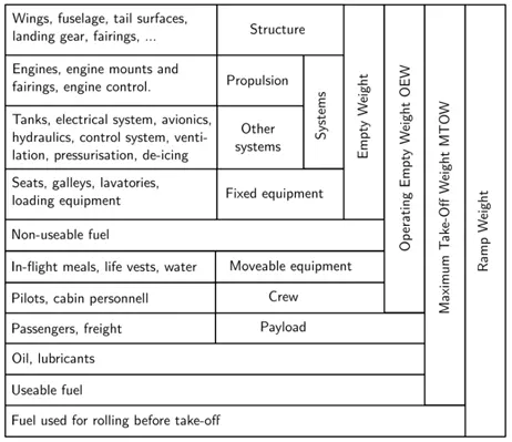
Table 1: Common Weight terms and their significance
Types of Aircraft
There are different types of Aircraft according to basic design, Principle of propulsion through air, and Design of wings. They are explained in figure below.
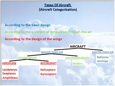
Figure 1: Types of Aircraft
LIGHTER-THAN-AIR
Aircraft whose lifting capability depends on being inflated with a gas such as hot air, hydrogen or helium.
HEAVIER-THAN-AIR
Aircraft whose lift is produced by a reaction between aerofoil and motion through the air.
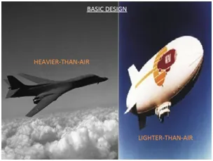
Figure 2: Type of Aircraft according to basic design
POWER DRIVEN
Aircraft, whose propulsion through the air is supported by engine power.
NON POWER DRIVEN
Aircraft whose propulsion through the air is derived from gravity and aerodynamic forces, and it is not supported by engine power. Eg: Glider
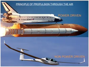
Figure 3: Types of Aircraft according to principle of propulsion
AEROPLANE (FIXED WINGS)
Aircraft whose lift is produced by a reaction between fixed wings and motion of the air about them.
ROTORCRAFT (ROTORY WINGS)
Aircraft whose lift is produced by rotating wings. Eg: Helicopter
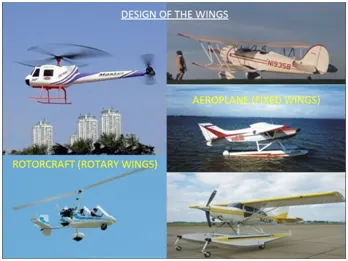
Figure 4: Types of Aircraft according to Design of wings
FEW EXAMPLES OF AIRCRAFT VEHICLES AND THEIR WEIGHT
|
TYPE |
EXAMPLE |
MTOW (TONNES) |
|
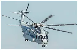
Heavy-lift cargo helicopter |
Sikorsky CH-53K King Stallion |
38.4 |
|
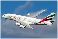
Passenger Airliner |
Airbus A380
|
575 |
|
Cargo freight |
Boeing 747 Dreamlifter
|
364 |
|
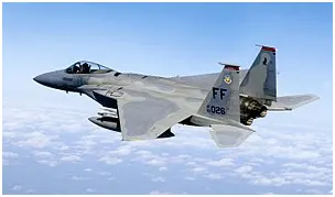
Air Superiority Fighter- An air superiority fighter is a fighter aircraft designed to seize control of an enemy airspace by establishing tactical dominance over the opposing air force |
F 15-EAGLE
|
40.5 |
|
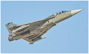
Multirole Fighter |
HAL -Tejas
|
14.66 |

- Is there any difference between ground speed and air speed?
Solution
YES. Wind speed and Air speed are different. Wind speed refers to the speed of wind and Air speed is the relative velocity between object and Air. The detailed explanation is given below.
Wind Speed
For a reference point picked on the ground, the air moves relative to the reference point at the wind speed. The wind has components in all three primary directions (north-south, east-west, and up-down) and is a vector quantity. In this figure, we are considering only velocities along the aircraft's flight path. A positive velocity is defined to be in the direction of the aircraft's motion. We are neglecting cross winds, which occur perpendicular to the flight path but parallel to the ground, and updrafts and downdrafts, which occur perpendicular to the ground.
Ground Speed
For a reference point picked on the ground, the aircraft moves relative to the reference point at the ground speed. Ground speed is also a vector quantity so a comparison of the ground speed to the wind speed must be done according to rules for vector comparisons.
Airspeed
The important quantity in the generation of lift is the relative velocity between the object and the air, which is called the airspeed. Airspeed cannot be directly measured from a ground position, but must be computed from the ground speed and the wind speed. Airspeed is the vector difference between the ground speed and the wind speed.
Airspeed = Ground Speed - Wind Speed
On a perfectly still day, the airspeed is equal to the ground speed. But if the wind is blowing in the same direction that the aircraft is moving, the airspeed will be less than the ground speed.
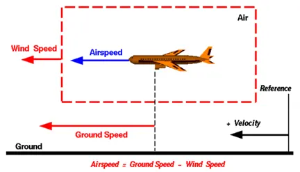
Figure 5: Graphical representation of Airspeed and Wind speed
If the aircraft is flying in the same direction as the wind is blowing, the aircraft experiences tailwind, and its ground speed is higher than its airspeed. On the other hand, if the wind is blowing against the direction the aircraft is traveling in, the aircraft experiences headwind, and its ground speed is lower than its airspeed.
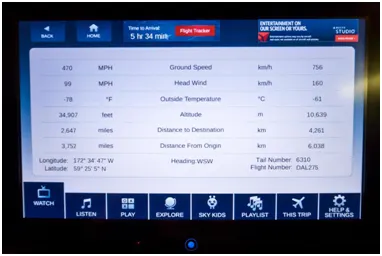
Figure 6: Actual data of Wind speed and Ground speed
Consider an example of aircraft that cruises at an airspeed of 500 miles per hour that has to cover a ground distance of 2,000 miles.
If there is no wind at all, then both the aircraft’s airspeed and ground speed would be the same 500 miles per hour, and the aircraft would reach its destination in four hours.
If there was a 100 miles per hour headwind – wind blowing against the aircraft’s direction of travel – the aircraft would still be traveling at an airspeed of 500 miles per hour. However, its ground speed would be just 400 miles per hour (100 miles per hour slower than its airspeed). And as such, it would take the aircraft five hours to reach its destinations.
Finally, if there was a 100 miles per hour tailwind – wind blowing in the same direction as the aircraft’s travel – the aircraft would still be traveling at an airspeed of 500 miles per hour, but its ground speed would be 100 miles faster. And, at 600 miles an hour, the aircraft would reach its destination in just three hours and twenty minutes.
3. Why is it not recommended to use aircraft engine power to move it on the ground at Airport?
Solution
The movement of aircraft with its own power on the ground is called Taxiing. An airplane uses taxiways to taxi from one place on an airport to another. But it is not advisable to move it on the ground due to the following reasons.
- Aircraft are designed to fly. When they’re going to spend more than 15 hours in the air, they need to perform as efficiently as possible. From getting the most power out of the engines to maximizing the lift from the wings, the main part of the design process is focused on the airborne aspect.
- Aircraft fuel is costly. Running on the ground with less efficiency consumes fuel which can actually use for flying.
- It is difficult to control in ground. It cannot reverse. Due to the wide open wings, pilot has to be careful while driving on the ground.
- Engine may get damaged due to foreign objects stuck into it.
- May cause accidents to ground crew.
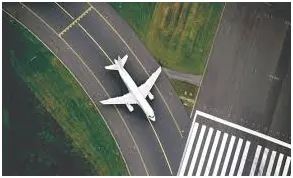
Figure 7: Taxiing of an Aircraft
4. How an aircraft is pushed to runway when its ready to take off?
Solution
The forward movement of an aircraft, usually with engines off, using the power of a specialized ground vehicle attached to or supporting the nose landing gear. It may occur for the movement of both in service and out of service aircraft. This will affect the promulgation of procedures and the required qualification for those occupying the flight crew seats on the aircraft during the manoeuvre. As part of out of service repositioning of aircraft supervised by maintenance personnel, it may follow the Pushback from a nose-in gate of an empty aircraft with engines off.
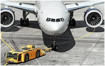
Figure 8: An Aircraft towed by a tug
5. Learn about take off power, tire design, rolling resistance, tire pressure, brake forces when landing.
Solution
1. Take off Power
Take off starts at time t0, with airspeed V0 and the runway may have an angle to horizontal of φ. Lift off occurs at time tg, after a distance of xg, usually at speed VLOF. Take off is completed when the aircraft has reached sufficient height to clear an obstacle 35ft high (50ft for military aircraft).
Finally, the climb out phase takes the aircraft to 500ft at the climb throttle setting.
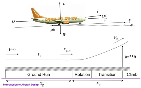
Figure 9: Forces acting on an aircraft during Take off
Ground Run
The ground run can either start at V0=0. The angle of attack is defined with respect to the thrust line. For aircraft with a tricycle landing gear the angle of attack is nearly zero. At a sufficient speed the nose is lifted up a little bit to achieve an optimum angle of attack. For aircraft with a tail wheel the angle of attack is very high. At an airspeed where the control surfaces are effective the angle of attack is decreased to decrease the drag and increase acceleration.
Lift off
In principle an aircraft can lift off once it has reached its stall speed, Vstall. At this airspeed it can increase its angle of attack αmax, with a resulting CLmax. This lift coefficient will generally satisfy L>W.
However, for safety reasons, the lift off speed is defined as VLOF =k1Vstall
Where, k1=1.10 is an indicative value which varies with type of aircraft.
Rotation and Transition
After lift off the aircraft rotates to deflect the velocity from nearly horizontal to a few degrees upward. The rotation lasts usually for a couple of seconds.
The transition stage follows, at the end of which the aircraft is required to clear a hypothetical obstacle.
The speed at the clearance of the obstacle, V2 =k2*Vstall
where k2=1.2
Take off
V1 is called the decision speed for multi engine aircraft. Below this speed, if one engine fails, the take off is aborted. Above this speed, if one engine fails, the take off is continued.
Take off field length: Distance from rest to obstacle clearance F The climb stage follows the transition stage. F The take off phase is usually considered to be complete at around 500ft once the flaps have been retracted.
Equations of motion
Total force applied to the aircraft parallel to the runway = F
The acceleration, a=dV/dt.
The velocity, V=dx/dt. F
In order to have a friction force, it must be that R>0,
R = W − L = W – ( ½) ρ* (V^2) S* CL
Where it is assumed that the runway’ s inclination is small.
The total force can be written as, ma = T − µW – (1/2)* ρ*(V^2)*S(CD − µCL )
2. Tire Design
When it comes to safety, tires are one of the most important components of aircraft. They help to absorb the shock of landing and provide cushioning. It also provides the necessary traction for braking and stopping of an aircraft.
An aircraft tire is designed to withstand extremely heavy loads while landing, take off, taxing, and parking. The number of wheels required for aircraft increases with the weight of the aircraft, as the weight of the aeroplane needs to be distributed more evenly.
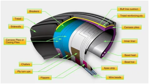
Figure 10 : Construction nomenclature of an aircraft tire
Bead
The tire bead is an important part of an aircraft tire. It anchors the tire carcass and provides a dimensioned, firm mounting surface for the tire on the wheel rim.
Carcass Plies
Carcass plies, or casing plies as they are sometimes called, are used to form the tire. Each ply consists of fabric, usually nylon, sandwiched between two layers of rubber.
Tread
The tread is the crown area of the tire designed to come in contact with the ground. It is a rubber compound formulated to resist wear, abrasion, cutting, and cracking.
Sidewall
The sidewall of an aircraft tire is a layer of rubber designed to protect the carcass plies. It may contain compounds designed to resist the negative effects of ozone on the tire.
Chine
Some tire sidewalls are mounded to form a chine. A chine is a special built-in deflector used on nose wheels of certain aircraft, usually those with fuselage mounted engines.
Types of Tires
A radial tire has the fiber strands of the ply fabric oriented with and at 90° to the direction of rotation and the tire sidewall. This restricts flexibility bidirectional and the flexibility of the sidewall while it strengthens the tire to carry heavy loads.
A bias-ply tire has the fabric bias oriented with and across the direction of rotation and the sidewall. Since fabric can stretch on the bias, the tire is flexible and can absorb loads. Tire strength is obtained by adding plies.
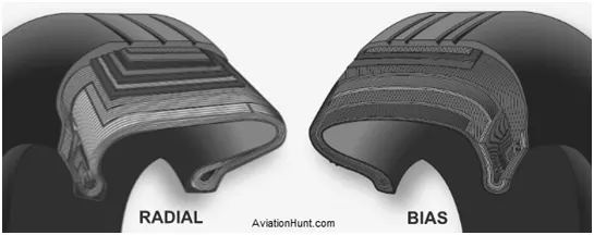
Figure 11 : Types of Tires
3. Tire Pressure
An improperly inflated aircraft tire can sustain internal damage that is not readily visible and that can lead to tire failure. Tire pressure should be measured at ambient temperature. Fluctuations of ambient temperature greatly affect tire pressure and complicate maintenance of pressure within the allowable range for safe operation. Tire pressure typically changes 1 percent for every 5 °F of temperature change.
When aircraft are flown from one environment to another, ambient temperature differences can be vast. Maintenance personnel must ensure that tire pressure is adjusted accordingly. For example, an aircraft with the correct tire pressure departing Phoenix, Arizona where the ambient temperature is 100 °F arrives in Vail, Colorado where the temperature is 50 °F. The 50° difference in ambient temperature results in a 10 percent reduction in tire pressure. Therefore the aircraft could land with underinflated tires that may be damaged due to over-temperature from flexing beyond design limits as described above. An increase in tire pressure before takeoff in Phoenix, Arizona prevents this problem as long as the tires are not inflated beyond the allowable limit provided in the maintenance data.
In addition to overheating, under inflated aircraft tires wear unevenly, which leads to premature tire replacement. They may also creep or slip on the wheel rim when under stress or when the brakes are applied. Severely under inflated tires can pinch the sidewall between the rim and the runway causing sidewall and rim damage. Damage to the bead and lower sidewall area are also likely. This type of abuse like any over flexing damages the integrity of the tire and it must be replaced. In dual-wheel setups, a severely underinflated tire affects both tires and both should be replaced.
Over inflation of aircraft tires is another undesirable condition. While carcass damage due to overheating does not result, adherence to the landing surface is reduced. Over a long period of time, over inflation leads to premature tread wear. Therefore, over inflation reduces the number of cycles in service before the tire must be replaced. It makes the tire more susceptible to bruises, cutting, shock damage, and blowout. [Figure 12]
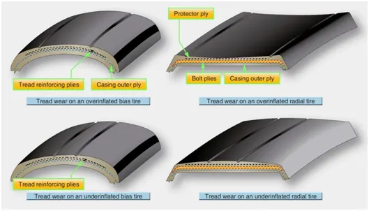
Figure 12 : Effect of tire pressure
4. Rolling Resistance
Tire rolling resistance is the energy that vehicle needs to send to tires to maintain movement at a consistent speed over a surface. In other words, it is the effort required to keep a tire rolling.
The rolling resistance force, Fr = Cr * M * g
Whre Cr is the coefficient of rolling friction, ‘M’ is the mass of vehicle and ‘g’ is acceleration due to gravity.
The different types of runways and their rolling resistance coefficients are given below.
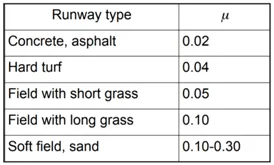
Table 2: Rolling Resistance coefficients for different types of runways
5. Brake forces when landing
Aircraft Landing Performance Calculation
Generally, the landing phase is split into four segments: approach, flare, transition and full braking segment. Figure shows the total process of landing.
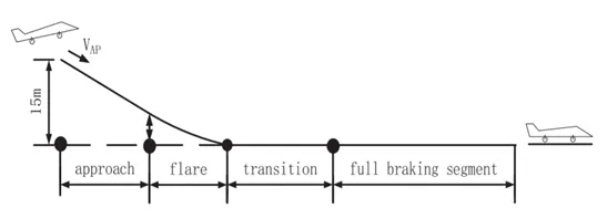
Figure 13: Aircraft Landing Process
An aircraft decelerates through its braking system, spoilers and thrust reverser during ground roll of landing after touchdown.

The above equation can be used to solve the distance of transition and full braking segment. However, the friction coefficients before and after braking system works are different values. The lift and drag coefficient before and after spoilers work are different values too. When thrust reverser plays a part in landing, it should be taken into consideration.
6. With necessary assumptions, calculate the force and power required to push / pull an aircraft by a towing vehicle.
Solution
For calculating Force and Power, we require specifications and dimensions of both Aircraft and Towing vehicle. So we have extracted parameters from Boeing 737 -200 aircraft and Eagle TT – 16 Towing vehicle.
Aircraft Specifications - Boeing 737-200
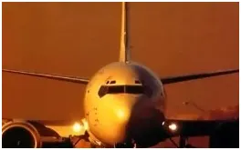
Figure 14: Boeing 737-200
|
Length |
100.16 ft |
30.53 m |
|
Wing Span |
93.01 ft |
28.35 m |
|
Height |
36.84 ft |
11.23 m |
|
Max Takeoff Weight |
115,500 lbs |
52,390 kg |
Table 3:SPECICFICATIONS OF EAGLE TT-16 Aircraft Tow Tractor
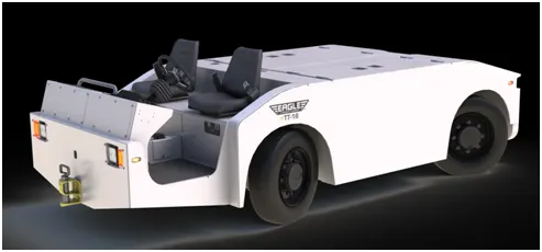
Figure 15: EAGLE TT-16
- Max Tow Weight: 155,000 lbs/ 70,307 kgs
- Length: 166 in / 4,216 mm
- Width: 72 in/1,829 mm
- Tires (front &rear): 215/75 R17.5 LR F
- Max Towing Speed: 4.5mph / 7.2 kph
- Weight of Towing Vehicle: 16,800 lbs / 7,620 kgs

Figure 16: Tire Specifications
Drag Coefficients
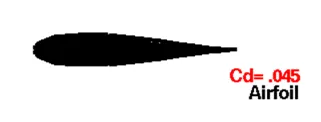
Figure 17: Drag Coefficient of Aircraft
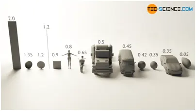
Figure 18: Drag Coefficient of Towing truck
Calculation of force and power to pull Aircraft
The main forces acting on the Towing truck are 1. Rolling Resistance force, 2. Aerodynamic Resistance.
Rolling Resistance = M* g
Where M= Mass of Aircraft + Mass of Towing truck = 60010 * 9.81 = 11.773kN
Aerodynamic Drag Resistance,Fad = 0.5 * Af* Cd* V^2
Since Aircraft and Towing vehicle has different Frontal area and Drag coefficients, we can calculate it separately.
Fad (Aircraft) = 0.5 * 1.25 * 0.045 * 318.37 * 2 * 2 = 35.2 N
Fad (Towing Vehicle) = 0.5 * 1.25 * 0.5 * 7.71 * 2 * 2 = 9.64 N
Total Aerodynamic Drag Resistance = 45.45 N
Total Force, F = 11819.42 N
Total Power in kW = F * Velocity = 11819.42 * 2/1000 = 23.64 Kw
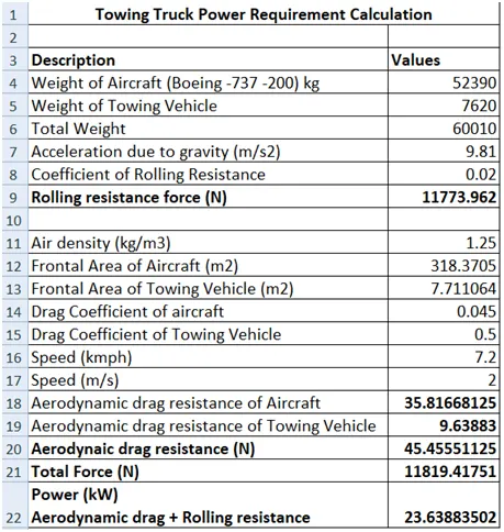
Table 4: Excel Calculations of Force and Power
- Design an electric powertrain with type of motor, it’s power rating, and energy requirement to fulfill aircraft towing application. Estimate the duty cycle range to control the aircraft speed from zero to highest. Make all required assumptions. Prepare a table of assumed parameters. Draw a block diagram of power train.
Solution
From previous calculations, Power required = 24kW
Assuming gear efficiency of 95%, Power of motor required = 25.2kW
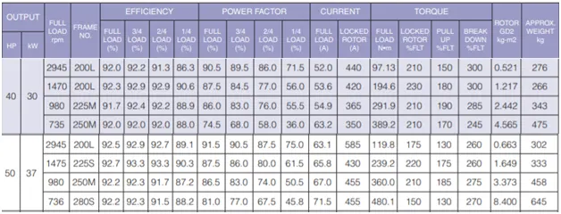
Table 4: ELECTRICAL CHARACTERISTICS - TECO - AESV2E / AESU2E Induction motor
To find the Gear Ratio
Max. Speed of the vehicle = 10 kmph
For a Wheel dia of 769mm, the Rated RPM of motor = 980
Converting 980 RPM to Kmph, we get 142kmph.
We require 10kmph for out vehicle. So gear ratio = 142/10 = 14 appx.
Torque,T= Force* Radius/(Gear ratio*GearEfficiency)
= 11819.41*0.3845/14*0.92=352.84Nm
From the above calculations, the 37kW Induction motor has been selected to meet the Torque requirements.
From the figure above, the motor ratings are given below.
Motor Type = Three phase Squirrel cage Induction motor
Motor Output Power = 37kW
Full load RPM = 980
Full load Torque = 360Nm
Efficiency = 92%
Current = 67A
Voltage = 400V / 50Hz
Calculation of Battery
Power required for the battery = Motor rating/ Inverter Efficiency
= 37000/0.9 = 41.111 kW
Energy of the battery for 4 hours of run,E = P * t = 41.111 * 4*3600 = 591998.4 kJ = 164.44kWh
For 500 V battery, the Ah rating = 164.44*1000/500 = 328Ah
The Battery rating is as follows:
500V, 328Ah, 165 kWh Li-Ion Battery
Duty cycle of Inverter from Zero to highest speed
The highest speed of Vehicle = 7.2kmph = 2m/s
To convert it in to RPM,
v = r × ω
Where:
v: Linear velocity, in m/s, r: Radius, in meter, ω: Angular velocity, in rad/s
The RPM to Linear Velocity formular is :
v = r × RPM × 0.10472
RPM = v/(r*0.10472) = 2/(0.3845*0.10472) = 49.67rpm
Speed of the motor(assuming 95% gear eff.) = 49.67 * 14 /0.95 = 732rpm
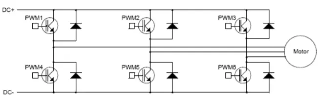
Figure 19: 3phase Invereter
To calculate duty cycle for max. speed of vehicle
Rated Power of motor = 37kW
P = 2*3.14*N*T
Since torque is constant, Power is proportional to N
Rated speed of the motor = 980rpm
P2/P1 = N2/N1
Where P1 is the rated power and P2 is the power at 732rpm.
P2= P1* (N2/N1) = 37 * (732/980) = 27.63 kW
Duty cycle at zero speed = 0
Duty cycle at maximum speed = P2/P1 = 27.63 / 37 = 0.75
Hence duty cycle should be varied from 0 to 75 % for o to 7.2kmph speed of vehicle.
Block Diagram of the Power Train
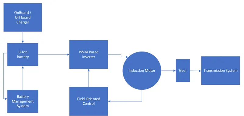
Figure 20: Block Diagram of power train
The above figure shows the block diagram of power train of Electric Towing vehicle of Aircraft. Li-Ion battery can be controlled by a BMS. The charger can be onboard / off board based on the requirement.
Induction motor is best suited for traction purpose due to high torque which can be controlled by using field oriented controller.
Assumptions made in the Towing vehicle parameter calculation
|
Aircraft and Towing vehicle Parameters REF : Table 3, Figure 16,17,18 |
||
|
Description |
Calculations |
Values |
|
Weight of Aircraft (Boeing -737 -200) kg |
52390 |
|
|
Weight of Towing Vehicle |
7620 |
|
|
Total Weight |
60010 |
|
|
Acceleration due to gravity (m/s2) |
9.81 |
|
|
Coefficient of Rolling Resistance |
0.02 |
|
|
Air density (kg/m3) |
1.25 |
|
|
Frontal Area of Aircraft (m2) |
11.23*28.35 |
318.3705 |
|
Frontal Area of Towing Vehicle (m2) |
4.216*1.829 |
7.711064 |
|
Drag Coefficient of aircraft |
0.045 |
|
|
Drag Coefficient of Towing Vehicle |
0.5 |
|
|
Speed (kmph) |
7.2 |
|
|
Radius of tire |
384.5mm |
|
|
MOTOR PARAMETERS –REF : TABLE 4 |
||
|
Motor Output Power |
37kW |
|
|
Full load RPM |
980rpm |
|
|
Full load Torque |
360Nm |
|
|
Efficiency |
92% |
|
|
Weight |
458kg |
|
|
Li-Ion Battery Ratings |
||
|
Battery Energy |
164.44 kWh |
|
|
Voltage |
500V |
|
|
Rating |
328Ah |
|
Conclusion
Different types of Aircrafts and the requirement of towing vehicle were studied. The Force, Torque and Power required for the Towing vehicle were calculated and based on that Motor and battery were selected. Duty cycle of the Inverter was also calculated for zero to maximum speed of the vehicle.
REFERENCES
- https://eagletugs.com/eagle-tt-electric-aircraft-tugs-ett-16
- https://bossforklifts.com/electric-aircraft-tow-tractor/
- https://www.engineeringtoolbox.com/plane-pull-force-people-d_2083.html
- https://www.globalair.com/aircraft-for-sale/Specifications?specid=1105
- https://schweisshydraulicdoors.com/airplane-size-chart.php#Rainbow%20Aircraft148
- https://ntrs.nasa.gov/search.jsp?R=19620005764
- https://www.aviationhunt.com/aircraft-tyre-construction/
- https://www.foreflight.com/products/foreflight-mobile/runway-performance/
- https://www.faa.gov/news/safety_briefing/2019/media/SE_Topic_19-12.pdf
- https://www.theairlinepilots.com/forumarchive/quickref/performance.pdf
- https://captainjetson.com/featured/taxiing-an-airplane-how-planes-move-on-the-ground/
- https://www.slideshare.net/caxnascimento/types-of-aircraft-presentation?from_action=save
- https://eie.uonbi.ac.ke/sites/default/files/cae/engineering/eie/DESIGN%20OF%20INVERTER%20DRIVE%20FOR%20AC%20INDUCTION%20MOTOR.pdf
- https://inverterdrive.com/group/Motors-AC/TECA2-200L-4-Pole-B3-High-Efficiency-AC-Motor-200/
- https://www.grc.nasa.gov/www/k-12/airplane/shaped.html