Week 8 - Challenge 4 - Bumper
OBJECTIVE : To Create the Bumper Plastic component through the given Class-A surface. To begin with, the tooling axis for the given Class-A Surface should be created meeting the requirements of the draft angle and at the end perform the Draft analysis on the model.
Take the Thickness of the component to be 3 mm
Report as follows :
Given Class-A Surface :-
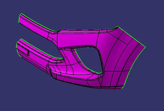
After analising for continuity in the surface joins lets us create tooling direction axis as follows :
let us draw tooling direction normal to the bottom surface as shown below :-
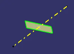
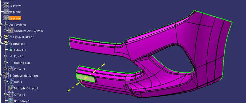
Now with the Tooling Direction let us run Draft analysis as follows:-
DRAFT ANGLE
When developing parts for plastic injection molding, applying a draft (or a taper) to the faces of the part is critical to improving the moldability of your part. Without it, parts run the risk of poor cosmetic finishes and may bend, break, or warp due to molding stresses caused by plastic cooling. Equally important, an absence of draft may prevent parts from ejecting from the mold, damaging not only the parts but possibly the mold itself—a costly and time-consuming detour.
DRAFT ANALYSIS OF CLASS A SURFACE
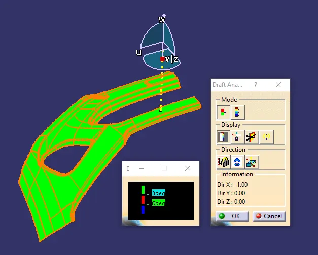
Use the compass fucnction to aling the compass to the tooling direction and lock the direction using lock function in the draft analysis tool bar. The surface is showing green colour so that the surface clears the minimum draft angle of 3 degree.
By using the analysis under the running point we can check draft angle on the individual faces. It shows how much draft on specific points when we move the cursor point. It is as shown below
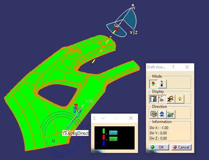
Green colour indicates values above 3 degree positive draft
Red colour indicates values between 3 and 0
orange colour indicates values below 0 degree
Now let us model
Creating class-B surface from A-Surface as follows :-
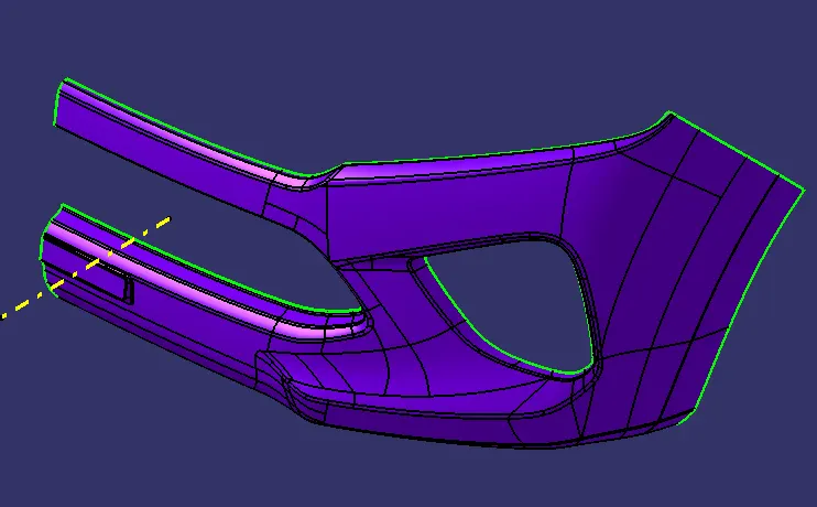
PINK Surface indicates Class-A surface and PURPLE Surface indicates Class-B Surface
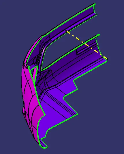
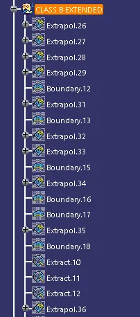
TREE STRUCTURE for Class-B AS FOLLOWS :-
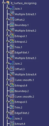
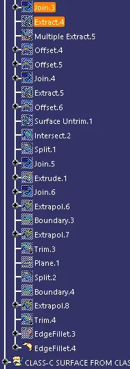
Let us create CLASS-C from Class-A surface boundary as follows:-
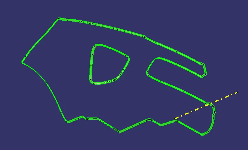
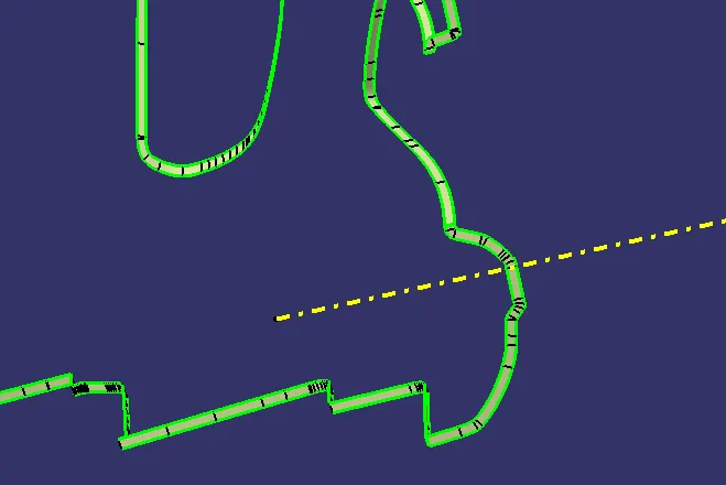
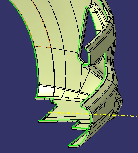
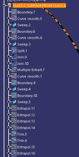
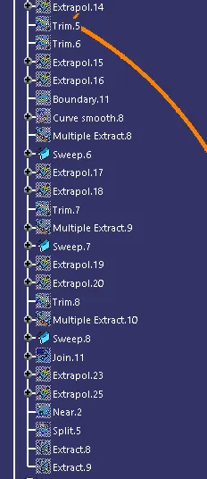
Tree structure as follows for CLASS-C surface as follows :-
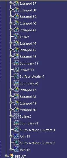
Now to trim the Class-C surface with the class A and class-B let us extrapolate Class-B surface
Joining Class-A , Class-B & Class C surface as follows :-
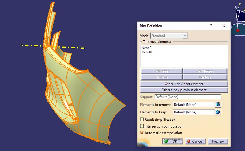
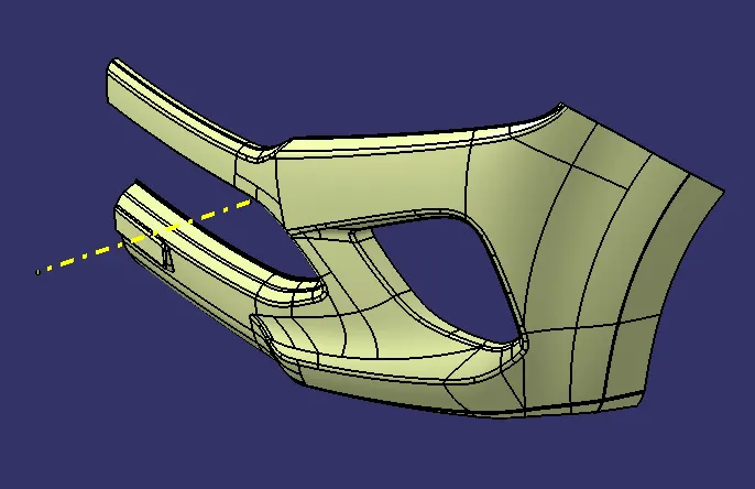
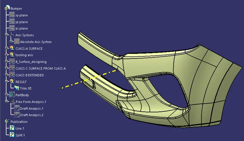
Complete simplified TREE STRUCTURE as follows
Complete simplified TREE STRUCTURE after SOLIDBODY conversion is as follows :
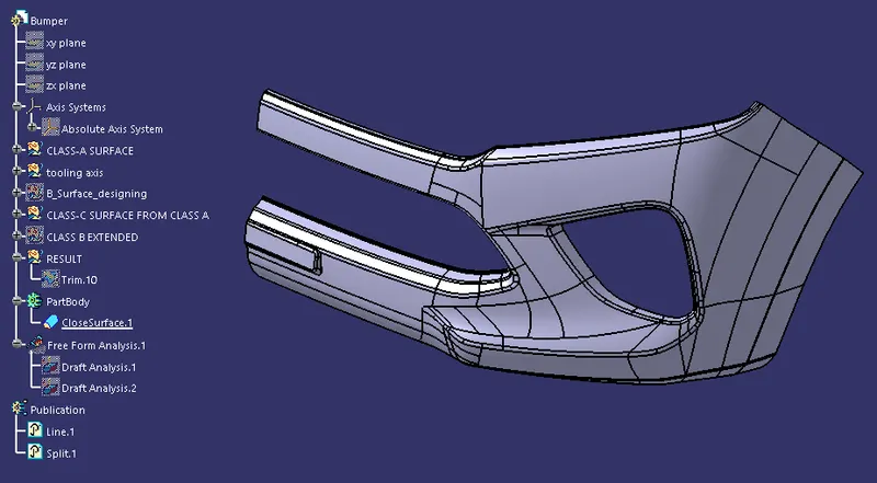
Different views after converting the Surface into Solid body in Part Design :
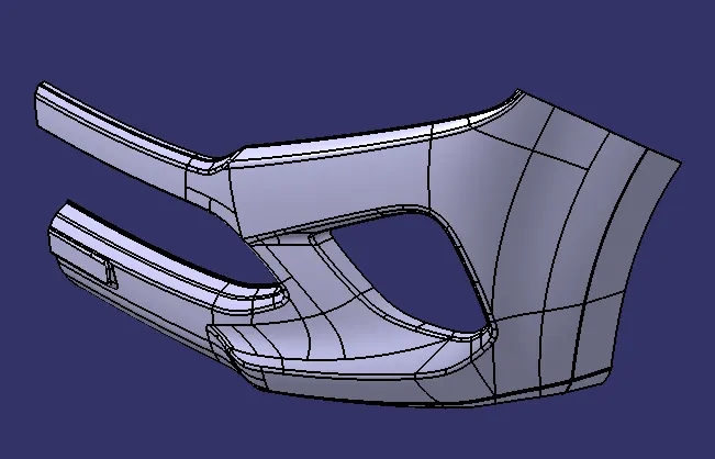
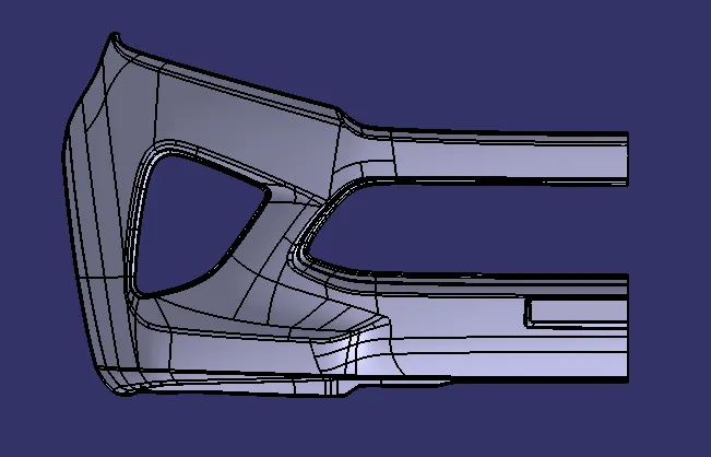
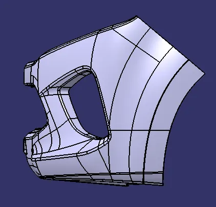
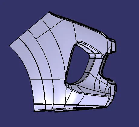
DRAFT ANALYSIS for the COMPONENT as follows :-
Draft analysis is done using featured draft analysis tool
Use the compass fucnction to align the compass to the tooling direction and lock the direction using lock function in the draft analysis tool bar.
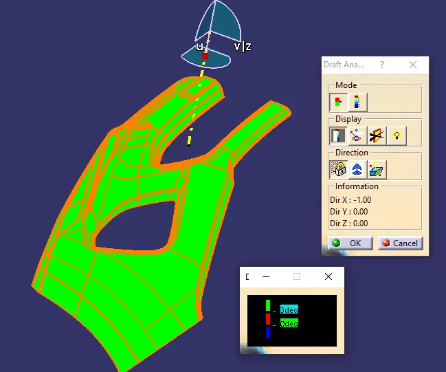
the surface is showing green colour so that the surface clears the minimum draft angle of 3 degree
By using the analyses under the running pointwe can check draft angle on the individual faces. It shows how much draft on specific points when we move the cursor point.
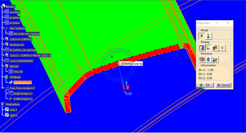
here since the Surface is at 2.99D , it does not clear the minimum draft angle which is 3 deg
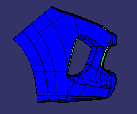
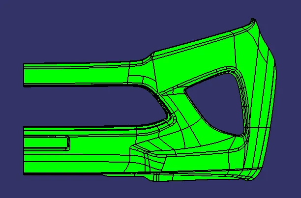
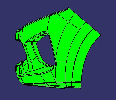
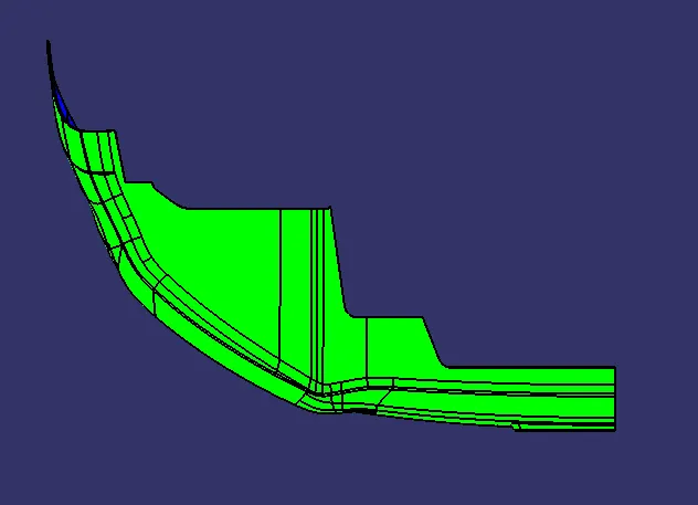
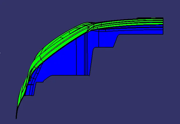
Green colour - above 3 degree positive draft
Red colour -between 3 and 0
blue colour- below 0 degree
Different views for draft colors are as follows :-
CONCLUSION
- Created the Bumper component using the given Class-A surface.
- The tooling axis for the given Class-A Surface is created which meeting the requirements of the draft angle.
- Draft analysis is done on the CLASS-A surface.
- Using the Close Surface feature, Solid body is created from the surface.
- Draft analysis is done on the Final Component.