Fender Design Challenge
FENDER DESIGN
OBJECTIVE:
Design the drip mounting area, Bumper, Sill, A-pillar and Baffle mounting area using the given master data.
INTRODUCTION:
Fender is the American English term for the part of an automobile or other vehicle body that frames a wheel. Its primary purpose is to prevent sand, mud, rocks and liquids and other road spray from being thrown into the air by the rotating tire.Sticky materials, such as mud, may adhere to the smooth outer tire surface, while smooth loose objects, such as stones, can become temporarily embedded in the tread grooves as the tire rolls over the ground. These materials can be ejected from the surface of the tire at high velocity as the tire imparts kinetic energy to the attached objects. For a vehicle moving forward, the top of the tire is rotating upward and forward, and can throw objects into the air at other vehicles or pedestrians in front of the vehicle. Fenders prevent injuries to the pedestrians and contain the motion of these particles.

We have two types of fenders
- Full bumper type
- Half bumper type
Full Bumper type
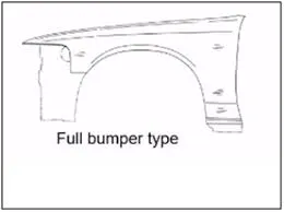
Full bumper type fender is the traditional type of fender which was used commonly in olden days. This type of fender have more material consumption as compare to present day fenders. Since the material used for manufacturing fenders will be steel or aluminium are generally increases the overall weight and expensive . so this type of fenders are not recommended in the market.
Half bumper type
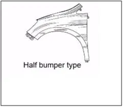
Half bumper fender is the type of fenders commonly used in the current markets. The material consumption is less compared to to full bumper fender. The scrap produced during part production is less also this design allows space for using plastic component at bumper. As the material consumption is less the weight of the body is also reduced which increase over all performance of the vehicle.
Fenders are mounted on 5 regions listed below and as shown in the diagram below
- Drip mounting
- A- pillar mounting
- Sill mounting
- Bumper mounting
- Splash mounting
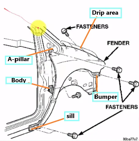
DESIGN AS PER MASTER SKETCH AND FENDER SKIN GIVEN :
Master sketch is as follows :
After designing the fender as per data provided and thickening it to 0.75mm, let us see in detail about the mounting points designed with relevant pictures as follows.
DESIGN 0F DRIP AREA MOUNTING :
- While designing the drip area we have to initially leave 200-300 mm for cowl top.
- For placing the headlamp we have to leave at least 150 mm at the front while designing the fender.
- Cowl top part consists wiper motor and its instruments.
- Three darts are added on the longer side of the drip area in order to provide the stiffness and adds strength to the part . This helps the fender to not to vibrate and impact the forces outside of the fender during motion of the vehicle.
- Embosses are provided on the mounting to strengthen them during fastening.
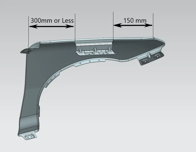
Different views on Drip mounting area are as follows
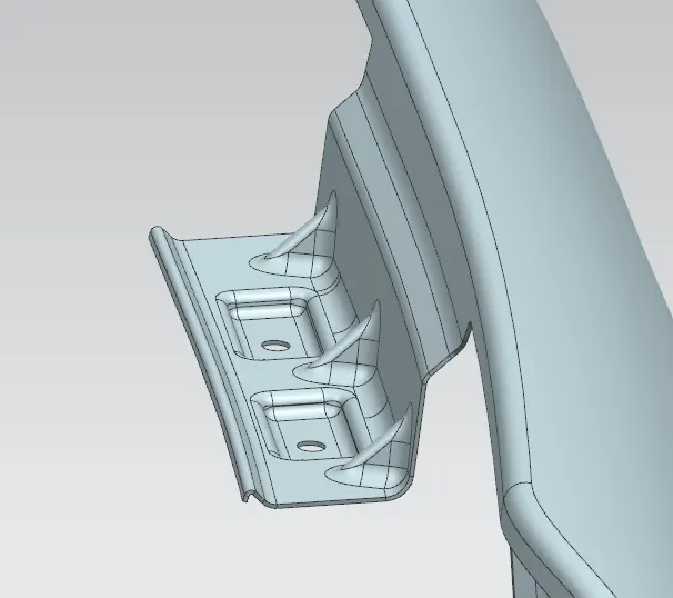
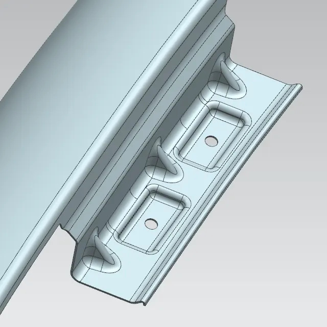
Drip area height needs to be less than 40mm.
DESIGN OF SILL MOUNTING AREA :
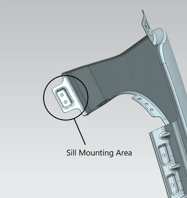
Sill is the panel directly below the bottom of the door supporting the floor and may be used to combine the floor and the body. The bottom end of the fender is mounted on the sill body for reinforcement of the fender panel , thus the sill mounting position is designed with holes and emboss. Fasteners are used to fix the fenders on the sill body.
Figure for sill mounting area is as follows
DESIGN OF BUMPER MOUNTING AREA :
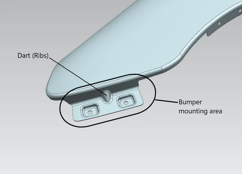
Bumper mounting area is used to fix the bumper to the fender with the help of the fasteners. Figure as follows.
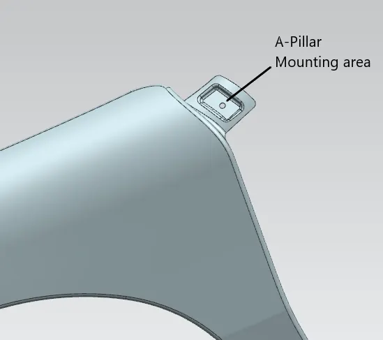
DESIGN OF A-PILLAR MOUNTING AREA :
A-pillar is the structural pillar that combines the body to the roof . this make the sides of the windshield rest. front fenders are fastened to the A-pillar to form a robust structure. Figure as follows.
DESIGN OF BAFFLE MOUNTING AREA :
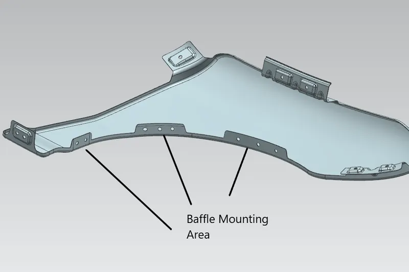
Baffle mounting or mudguard are clip fit type of mounting on the inner side of the fender arch over the Tyre. It protects the car engine compartment and pedestrians from causing injuries from chip out debris on the road when the car is in motion. They are mounted on the fender using a special type of locking clips which are made up of plastics. Figure as follows.
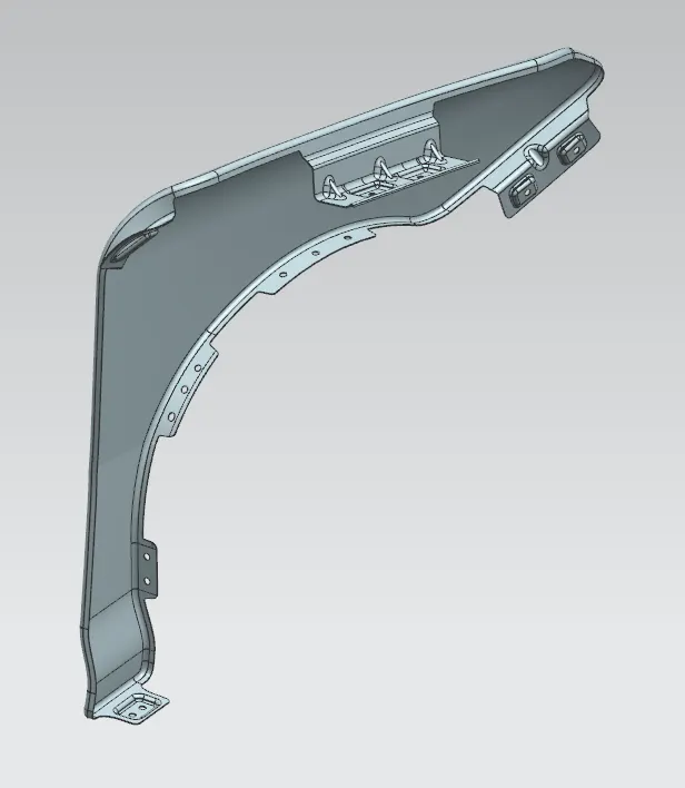
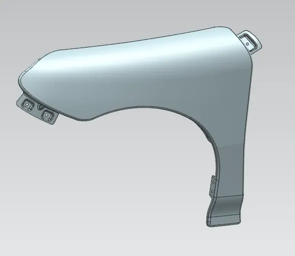
DIFFERENT VIEWS OF FENDER DESIGNED :
CONCLUSION :
Design of fender is completed with the help of NX-CAD tool by following the master section and given design guidelines.