Week 10- Assembly Workbench
AIM :
To create part models and assemble the components using the 2D drawings which were provided.
OBJECTIVE :
- To create the various part models from the 2D drawings.
- To asseble the part models into a single component.
- To create the 2D drawings of the components which were created.
QUICK RETURN MECHANISM
Procedure :-
1) Create a all sketch by using positioned sketch command USING the 2D drawings given.
2) Ensure that all the sketches in iso- constrained.
3) Let us create a Product assembly file.
4) Creat Main REFERENCE sets named as skeleton
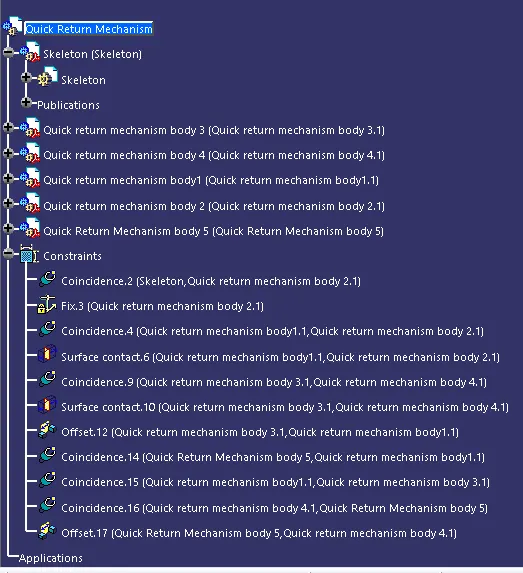
5) Assemble all the parts using constraints such as Coincidence, contact , Offset, fix etc using reference geometry.
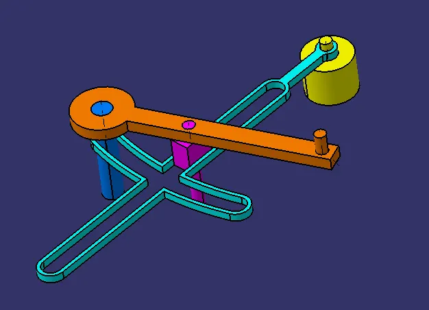
ASSEMBLY
FEATURE TREE
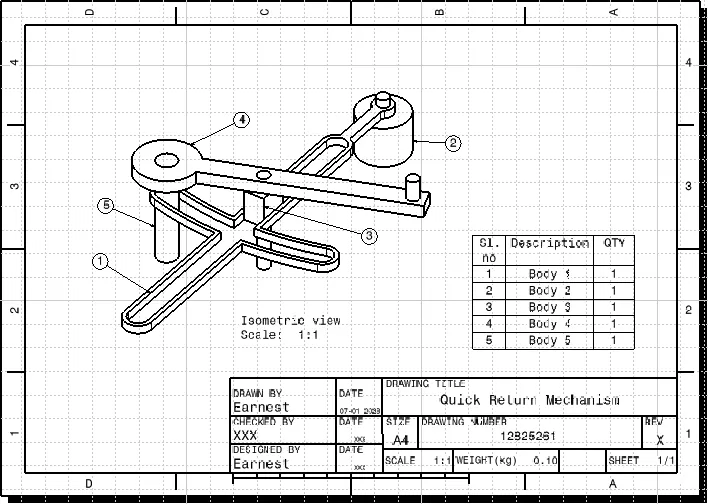
ASSEMBLY DRAWING
PART 1
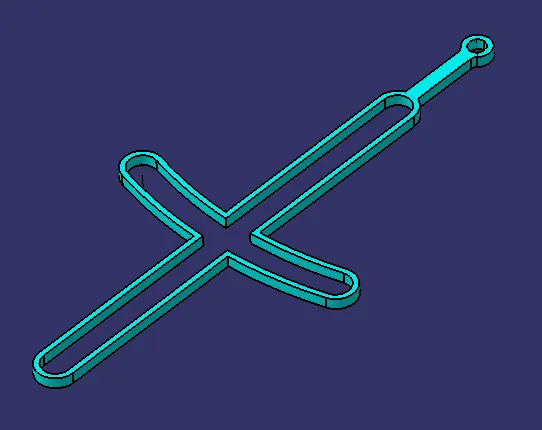
DRAWING 1
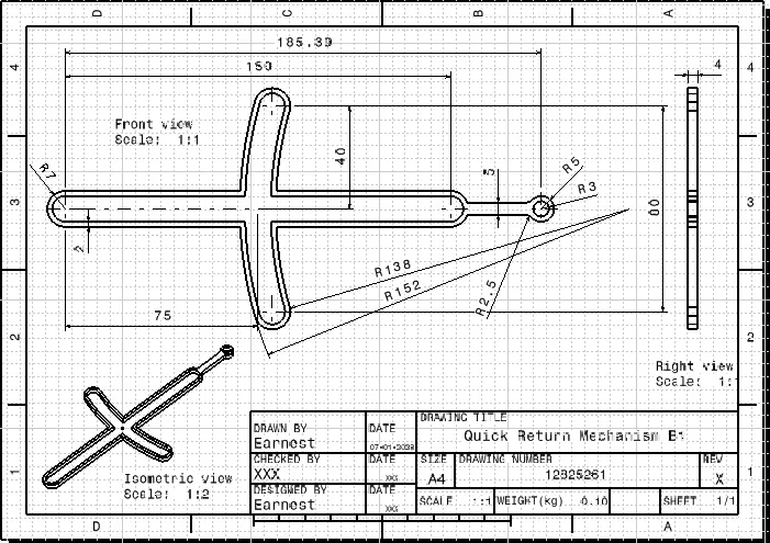
PART 2
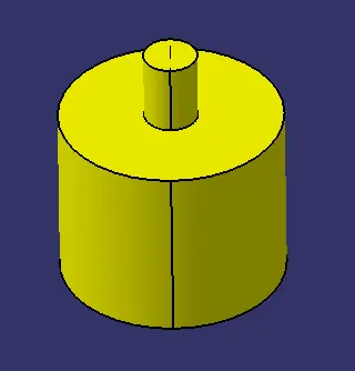
DRAWING 2
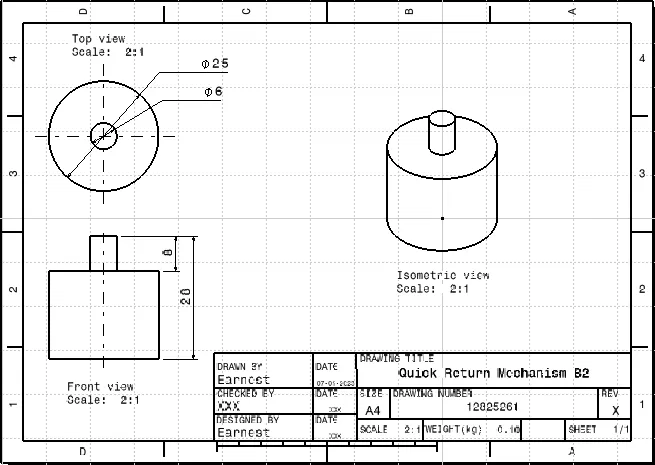
PART 3
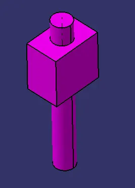
DRWAING 3
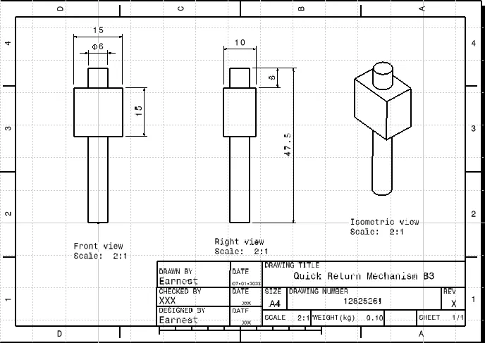
PART 4
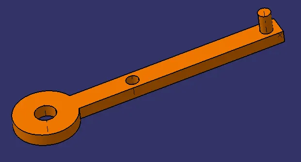
DRAWING 4
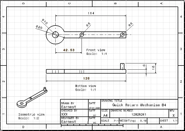
PART 5
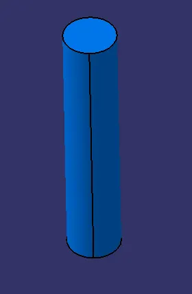
DRAWING 5
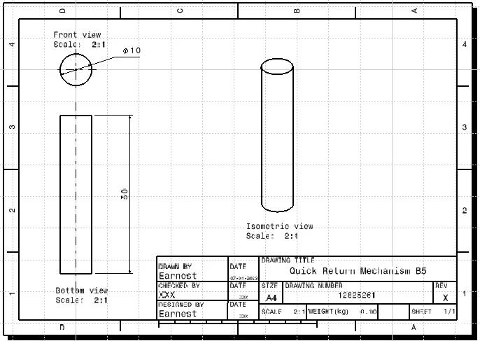
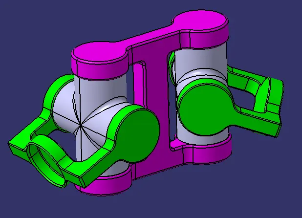
CV JOINT
Procedure :-
1) Create a all sketch by using positioned sketch command USING the 2D drawings given.
2) Ensure that all the sketches in iso- constrained.
3) Let us create a Product assembly file.
4) Creat Main REFERENCE sets named as skeleton
5) Assemble all the parts using constraints such as Coincidence, contact , Offset, fix etc using reference geometry.
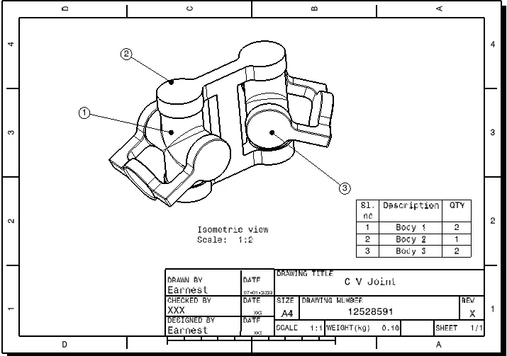
ASSEMBLY
FEATURE TREE
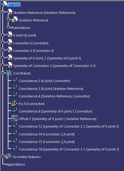
ASSEMBLY DRAWING
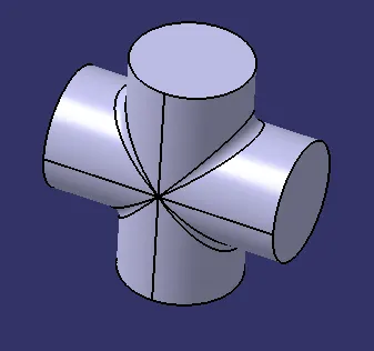
PART 1
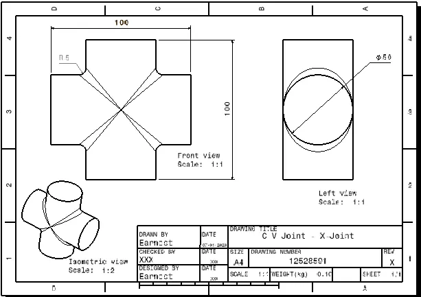
DRAWING 1
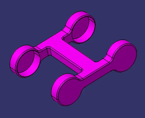
PART 2
DRAWING 2
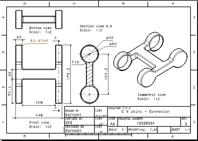
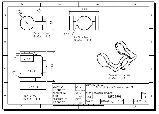
PART 3
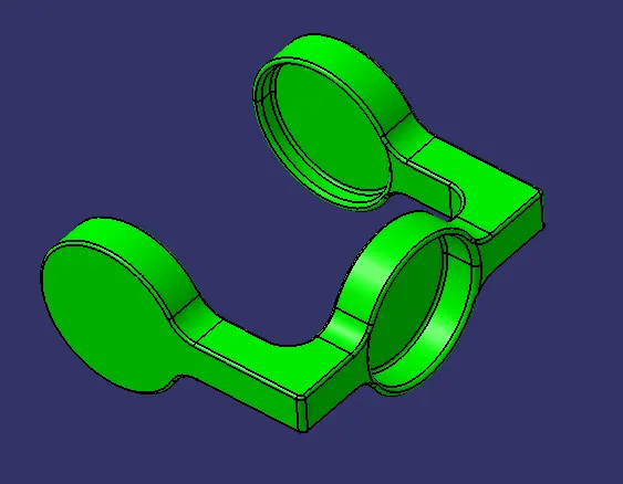
DRAWING 3
CONCLUSION :
- The part components and their respective assemblies were created.
- The 2D drawings of the components were created.
- Necessary files and images were attached.
Note :-
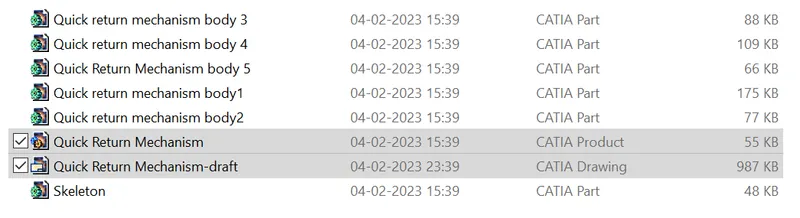
ZIP file consists of CATproduct file, CATpart file & CATDrawing file as follows :
Assembly 1
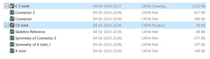
Assembly 2