Week 11 - Final project
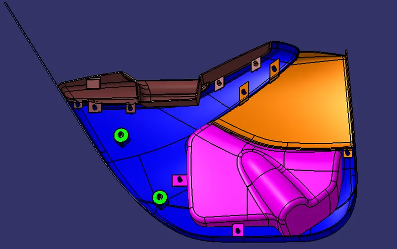
OBJECTIVE : To develop vehicle interior door trim panel by using CATIA V5 With given class-A surface along with the master sections and also create the B-side attachment feature as per design rules.
INTRODUCTION :
The door panel is the interface between the interior of the car and inner working of the door. Generally, the door panel is divided into parts for easy designing like arm rest, map pocket, Lower substrate. These require one of the toughest requirements amoung the interior parts of the car. This should be designed to with stand the load while being less than 2mm thickness and also to protect the occupants during collisions.
The panel covers the inside of door trim where various electrical components of the car are connected. We design the plastic side of door trim panel which is attached to the sheet metal through various B-side features.
Let us now see about the different types of surfaces used in designing
Class-A Surfaces :-
In automotive design a Class-A surface in any of a set of from surface of high efficiency and quality. Although strictly its nothing more than saying have curvature alignement to ideal aesthetical reflection quality, many people interpret class-A surface to have G2 or even G3 curvature continuity to one another. Class-A surface is creating by using computer Aided digital applications. Class-A surface modellers are also called digital sculptors in the industry.
Class-B Surface :-
Class B surface are Engineering Surfaces which are invisible to the eyes or often on the back side of the Class A surface. It is mainly the thickness of the component or Class A. These surfaces need to be designed as per the Class A surface i.e., the continuity, thickness of the component, functionality etc should be maintained. These surfaces include the main engineering features such as Screw bosses, Ribs, Snaps, Stiffeners and fixations. B surfaces also do not contain any aesthetic styling content and textures since it is not visible to eyes.
Class- C Surface :-
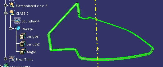
Class C surfaces are connectors between Class A and Class B surfaces. This surface connects both A and B surfaces along the tooling Axis. It contains the draft as per the design. It is basically the thickened surface between both A and B surface.
Tooling Axis:
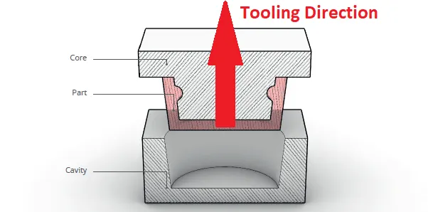
Tooling Axis is the direction in which the Mold opens and closes. Part Drafts are generally given along this axis.
DESIGN METHODOLOGY OF DOOR TRIM PANEL is as follows :-
- Tooling Axis Creation
- Class-A analysis
- Class B-surface Creation
- Class-C surface Creation
- Solidbody Creation using closed surface
- Draft Analysis
DOOR TRIM PANEL DESIGN :
The door panel is divided into four parts. There are as follows
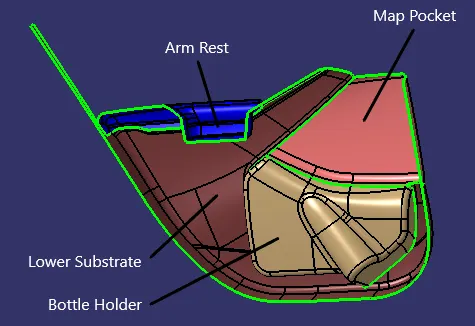
- Arm Rest.
- Lower substrate.
- Map Pocket.
- Bottle Holder.
Let us now create Solidbodies for all the above parts :-
1) ARM REST
After checking the continuity of given Class A surface, let us improve its surface.
Tooling Axis Creation :
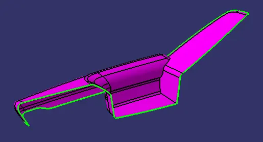
Creating Tooling axis for class A surface by extracting the bottom surface and creating a line with a point on the extracted surface.
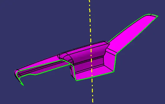
DRAFT ANALYSIS OF CLASS A SURFACE
Use the compass fucnction to aling the compass to the tooling direction and lock the direction using lock function in the draft analysis tool bar. The surface is showing green colour so that the surface clears the minimum draft angle of 3 degree.
By using the analysis under the running point we can check draft angle on the individual faces. It shows how much draft on specific points when we move the cursor point
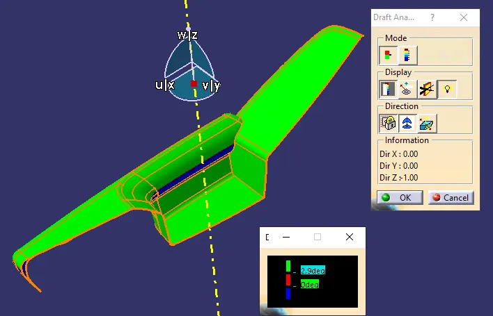
The pocket section does not clear and needs side core tooling axis which can be neglected in this project.
The given Class-A surface is continuos and we can proceed
CLASS B SURFACE CREATION :-
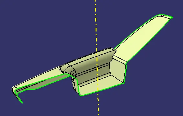
CLASS C SURFACE CREATION
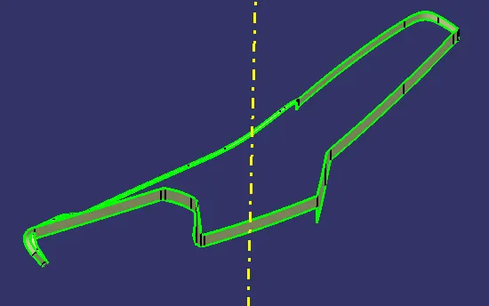
Let us do the final Trims with class A, Class B & Class C surfaces as follows :-
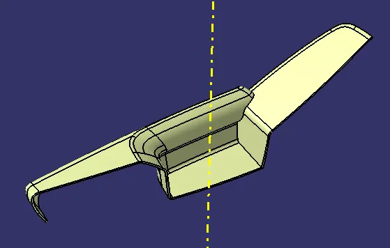
After Solidbody conversion Using close surface command in Part design workbench as follows :-
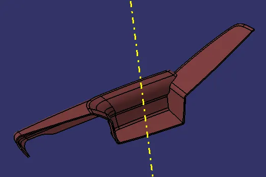
Let us carry on Draft analysis for the component :
Use the compass fucnction to aling the compass to the tooling direction and lock the direction using lock function in the draft analysis tool bar. The surface is showing green colour so that the surface clears the minimum draft angle of 3 degree.
By using the analysis under the running point we can check draft angle on the individual faces. It shows how much draft on specific points when we move the cursor point
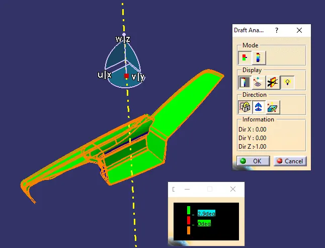
In the above Image, draft is clearing for 2.9 deg.
The pocket section does not clear and needs side core tooling axis which can be neglected in this project.
Different views are as follows :-
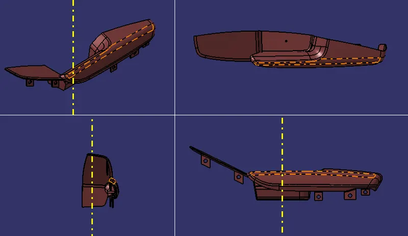
2) Lower Substrate
After checking the continuity of given Class A surface, let us improve its surface.
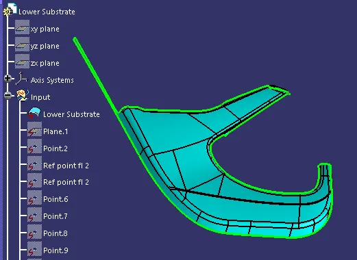
Tooling Axis Creation :
Creating Tooling axis for class A surface by extracting the bottom surface and creating a line with a point on the extracted surface.
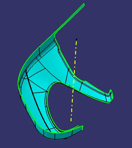
DRAFT ANALYSIS OF CLASS A SURFACE
Use the compass fucnction to aling the compass to the tooling direction and lock the direction using lock function in the draft analysis tool bar. The surface is showing green colour so that the surface clears the minimum draft angle of 3 degree.
By using the analysis under the running point we can check draft angle on the individual faces. It shows how much draft on specific points when we move the cursor point
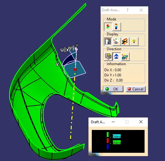
The given Class-A surface is continuos and we can proceed And draft angle is apt.
CLASS B SURFACE CREATION :-
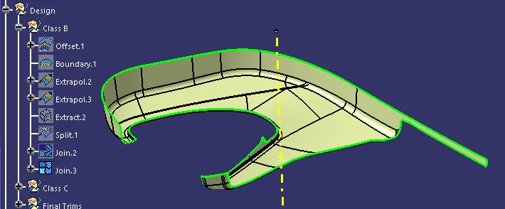
CLASS C SURFACE CREATION
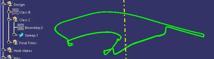
Let us do the final Trims with class A, Class B & Class C surfaces as follows :-
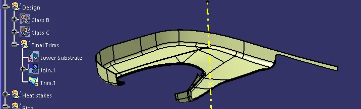
After Solidbody conversion Using close surface command in Part design workbench as follows :-
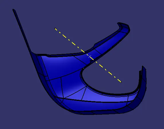
Let us carry on Draft analysis for the component :
Use the compass fucnction to aling the compass to the tooling direction and lock the direction using lock function in the draft analysis tool bar. The surface is showing green colour so that the surface clears the minimum draft angle of 3 degree.
By using the analysis under the running point we can check draft angle on the individual faces. It shows how much draft on specific points when we move the cursor point
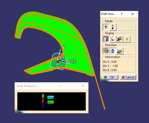
In the above Image, draft is clearing for 3 deg.
Different views are as follows :-
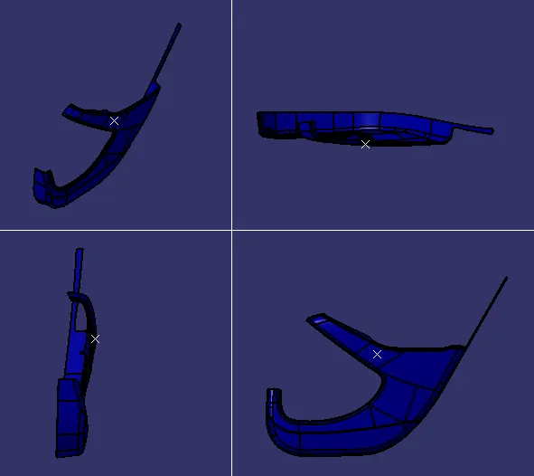
3) Map Pocket
After checking the continuity of given Class A surface, let us improve its surface.
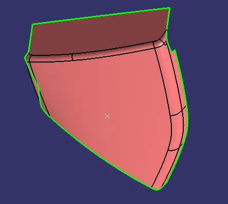
Tooling Axis Creation :
Creating Tooling axis for class A surface by extracting the bottom surface and creating a line with a point on the extracted surface.
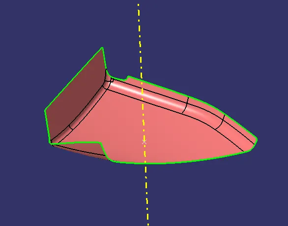
DRAFT ANALYSIS OF CLASS A SURFACE
Use the compass fucnction to aling the compass to the tooling direction and lock the direction using lock function in the draft analysis tool bar. The surface is showing green colour so that the surface clears the minimum draft angle of 3 degree.
By using the analysis under the running point we can check draft angle on the individual faces. It shows how much draft on specific points when we move the cursor point
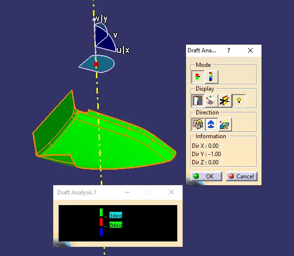
The given Class-A surface is continuos and we can proceed
CLASS B SURFACE CREATION :-
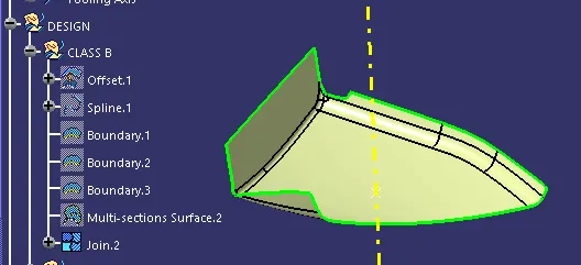
CLASS C SURFACE CREATION
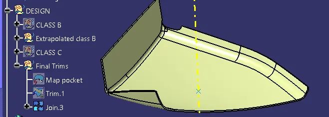
Let us do the final Trims with class A, Class B & Class C surfaces as follows :-
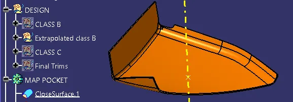
After Solidbody conversion Using close surface command in Part design workbench as follows :-
Let us carry on Draft analysis for the component :
Use the compass fucnction to aling the compass to the tooling direction and lock the direction using lock function in the draft analysis tool bar. The surface is showing green colour so that the surface clears the minimum draft angle of 3 degree.
By using the analysis under the running point we can check draft angle on the individual faces. It shows how much draft on specific points when we move the cursor point
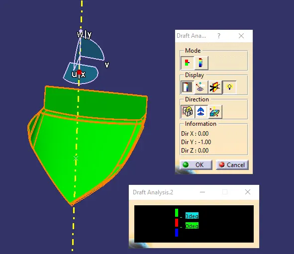
In the above Image, draft is clearing for 3 deg.
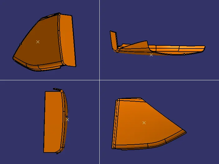
Different views are as follows :-
4) Bottle Holder
After checking the continuity of given Class A surface, let us improve its surface.
Tooling Axis Creation :
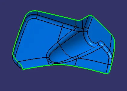
Creating Tooling axis for class A surface by extracting the bottom surface and creating a line with a point on the extracted surface.
DRAFT ANALYSIS OF CLASS A SURFACE
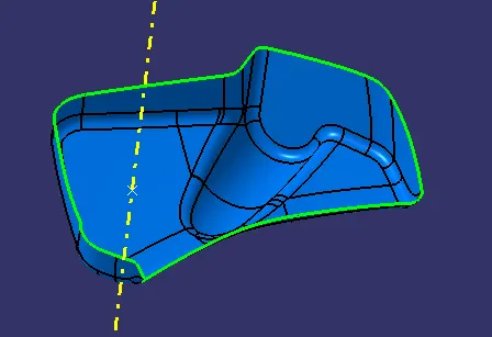
Use the compass fucnction to aling the compass to the tooling direction and lock the direction using lock function in the draft analysis tool bar. The surface is showing green colour so that the surface clears the minimum draft angle of 3 degree.
By using the analysis under the running point we can check draft angle on the individual faces. It shows how much draft on specific points when we move the cursor point
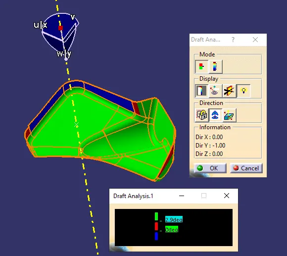
Here few surfaces do not clear for draft angle 3 Degree, we can neglect here in this project
The given Class-A surface is continuos and we can proceed.
CLASS B SURFACE CREATION :-
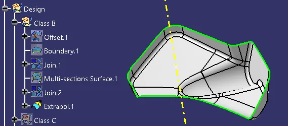
CLASS C SURFACE CREATION
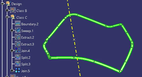
Let us do the final Trims with class A, Class B & Class C surfaces as follows :-
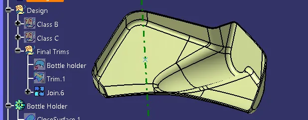
After Solidbody conversion Using close surface command in Part design workbench as follows :-
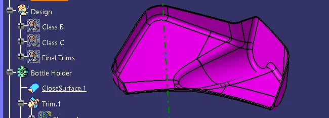
Let us carry on Draft analysis for the component :
Use the compass fucnction to aling the compass to the tooling direction and lock the direction using lock function in the draft analysis tool bar. The surface is showing green colour so that the surface clears the minimum draft angle of 3 degree.
By using the analysis under the running point we can check draft angle on the individual faces. It shows how much draft on specific points when we move the cursor point
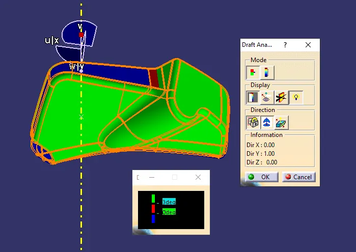
In the above Image, few surfaces do not clear for draft angle 3 Degree. We can neglect here in this project
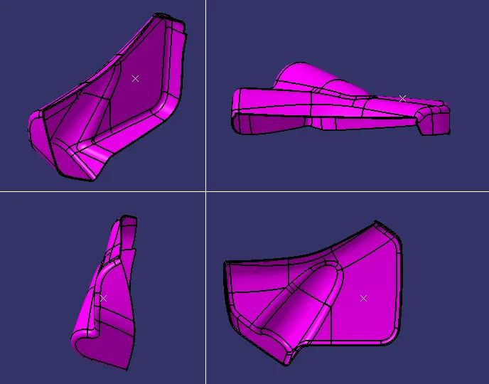
Different views are as follows :-
Now let us create Flanges in reference to the master section given :-
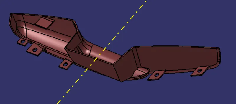
1) Arm Rest Flanges
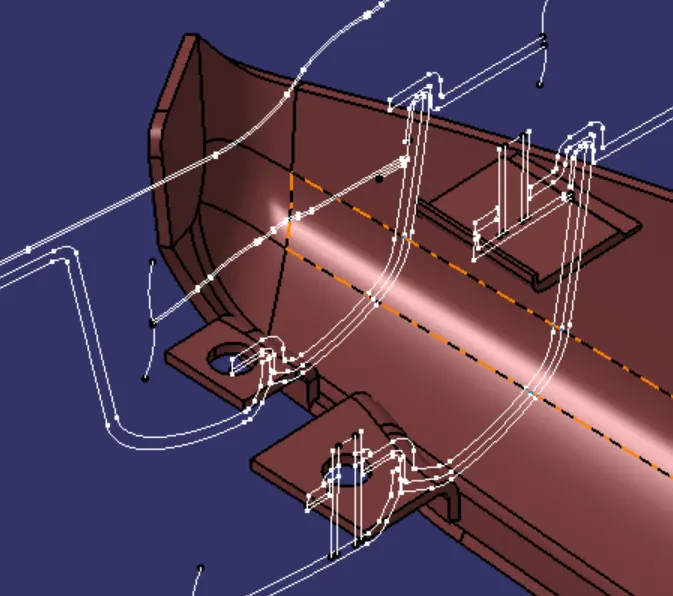
2) Map Pocket Flanges
Flange 1
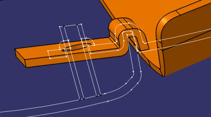
Flange 2
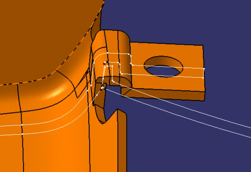
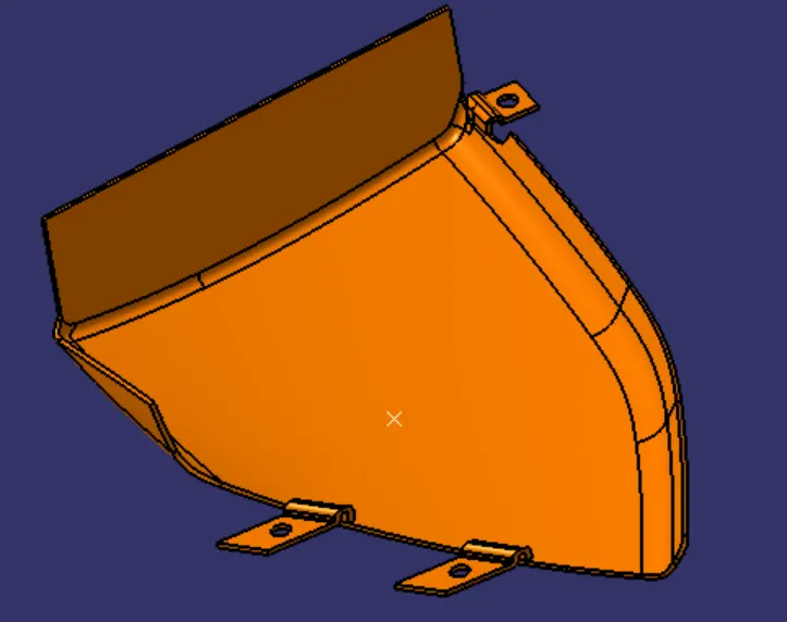
3) Bottle Holder Flanges
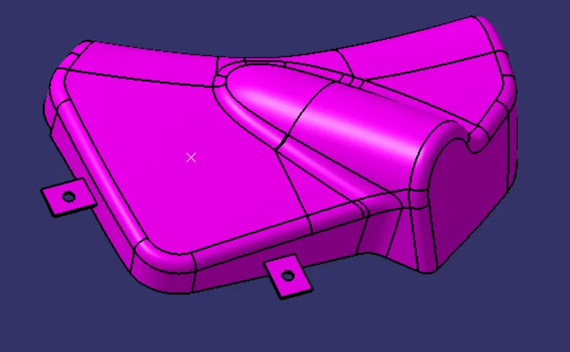
Now let us create B-side features as per Design Standards on the Lower substrate.
Design Standards as follows :-
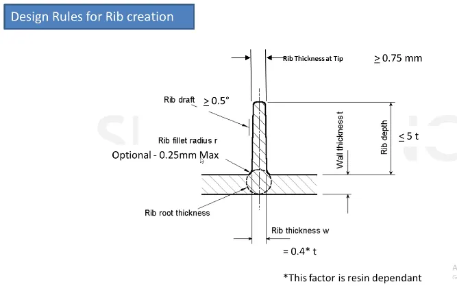
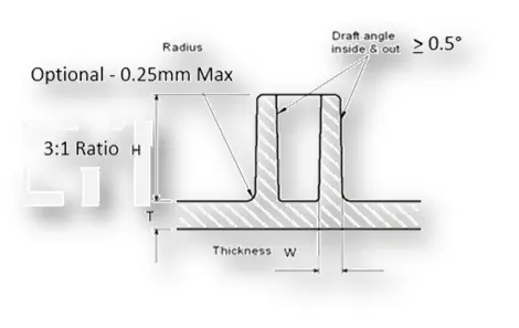
General Guidelines for Bosses :-
- Draft - 0.5 degrees on the walls of boss
- Thickness - Typically 40%* of the nominal wall at the base.
- Height to Diameter Ratio - 3:1
- Radii - 0.25mm maximum radii.
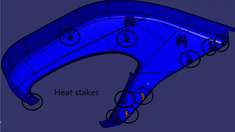
Heat Stakes with reference to master section given in the Lower substrate as follows
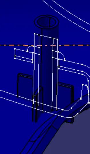
Draft Analysis for the Heat stakes along tooling direction is as follows :-
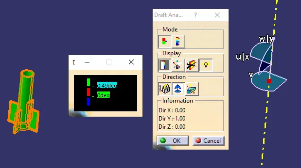
In the above Image, draft is clearing for 5 deg.
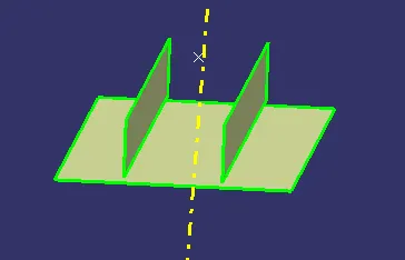
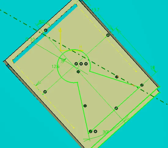
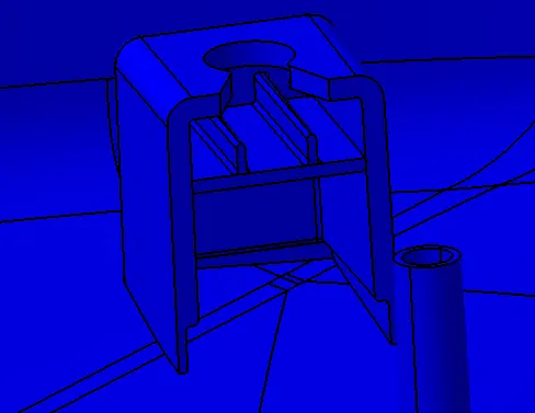
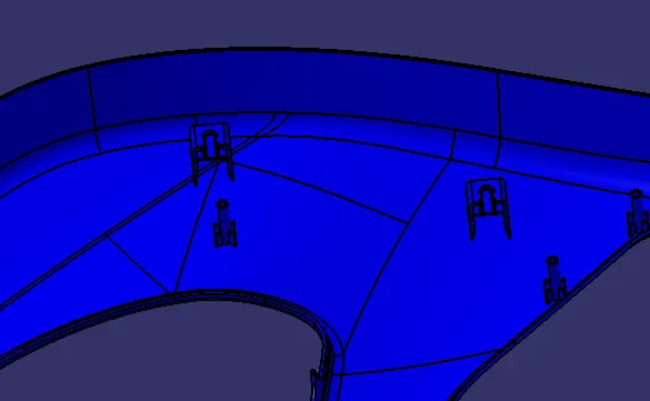
Let us create DOG HOUSES on the Lower substrate as follows :-
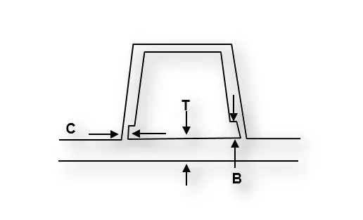
DESIGN STANDARDS for a Dog house is as follows
"C" is where the doghouse contacts the backside of the surface
-
Doghouse wall thickness at the intersection of the part wall ( C ) should be 40% or less than the main wall stock ( T ).
-
The height of ( B ) should be between 3.0 – 6.0 mm
Creating them in Lower Substrate :-
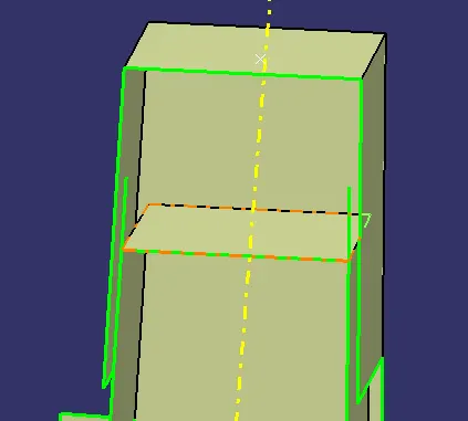
Draft Analysis for the DOG HOUSE along sidecore Axis is as follows :-
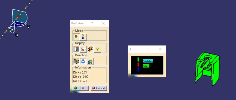
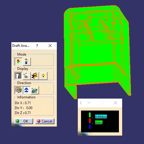
In the above Image, draft is clearing for 5 deg.
PUSH PIN:
The push pins are used for fastening or joining two objects which is made up of plastic. The below image shows the push pin.The push pins are created by extracting the given part body and make them a solid body.
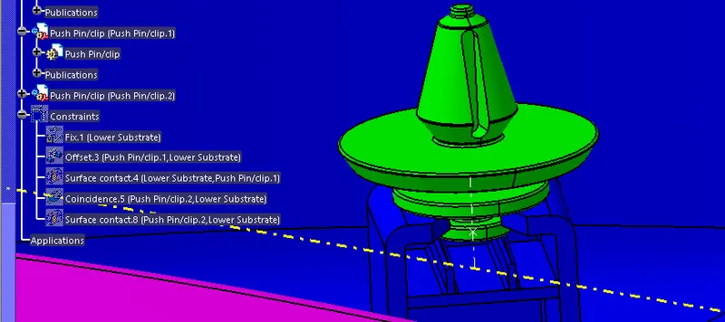
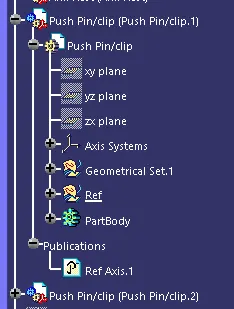
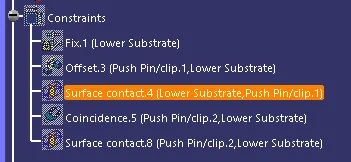
Tree Structure for Product file and assembly Constraints as follows :-
1)Product
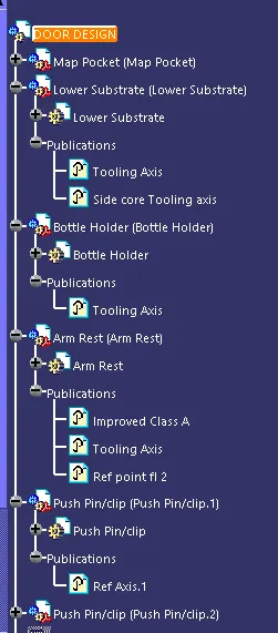
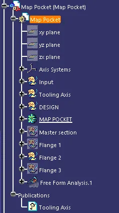
2)Map Pocket
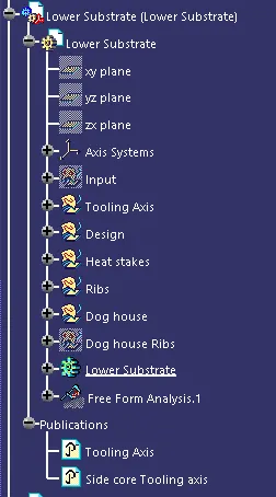
3) Lower Substrate
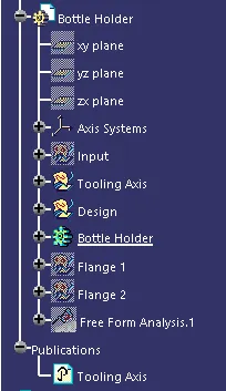
4) Bottle Holder
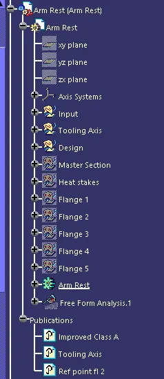
5) Arm Rest
6) PushPin Clip
Final Door Trim Assembly as follows :-