Advanced Sheet Metal Design Using NX Cad Challenge_7_ Metal bracket-II
OBJECTIVE:
To write a detailed report on Sheet Metal Component with good explanation on Sheet Metal modelling tools applied throughout the modelling. Also attach the Final model Images (Min. 4 images) of Sheet Metal Bracket.
The main importance of this project is to model a sheet metal bracket with some advanced features of sheet metal operations like Advanced flange, Gussets to provide the bracket with stiffening feature.
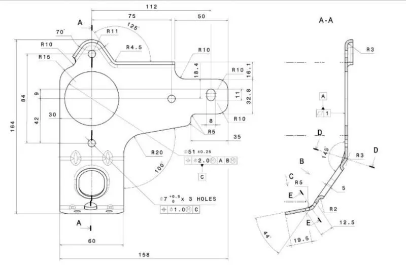
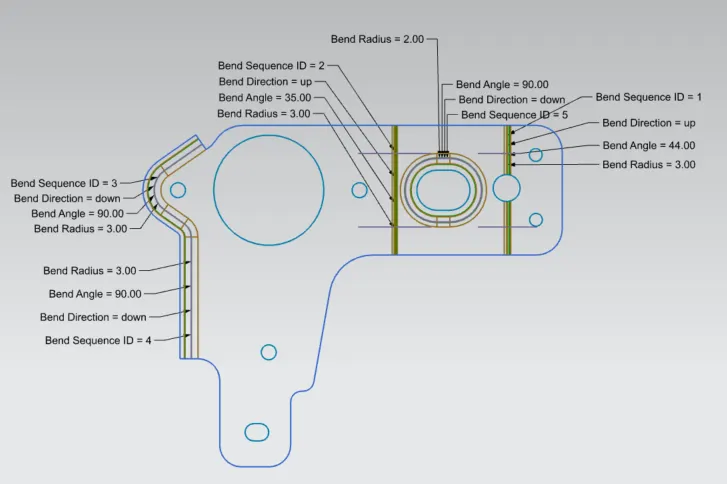
Given drawing as follows :
INTRODUCTION:
A bracket is an architectural element: a structural or decorative member. It can be made of wood, stone, plaster, metal, or other media. It projects from a wall, usually to carry weight and sometimes to strengthen an angle.In mechanical engineering a bracket is any intermediate component for fixing one part to another, usually larger, part. What makes a bracket a bracket is that it is intermediate between the two and fixes the one to the other. Brackets vary widely in shape, but a prototypical bracket is the L-shaped metal piece that attaches a shelf (the smaller component) to a wall (the larger component): its vertical arm is fixed to one (usually large) element, and its horizontal arm protrudes outwards and holds another (usually small) element.
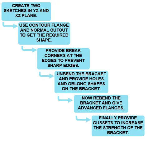
DESIGN METHODOLOGY: The flowchart is as follows:
Description (Features used while designing):
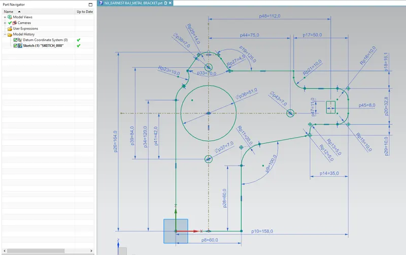
- Sketch: The profile that needs to be drawn for featuring is done in sketch command.It is a 2D representation
Sketch-1 as shown below :
Sketch-2 as shown below :
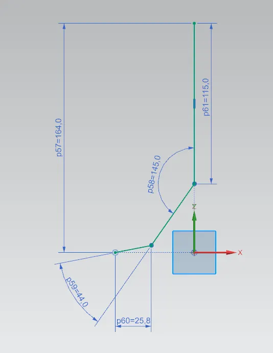
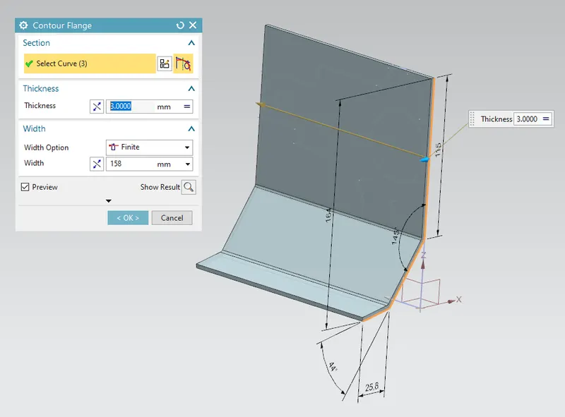
- Counter Flange: It is used to create flanges as per the required shape. Using sketch-2 as shown below
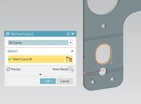
- Normal Cut Out: It is a feature used to cut the sheet metal at the required profile normally. Using sketch-1.
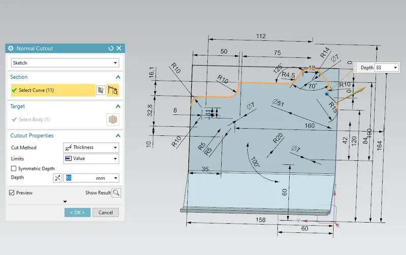
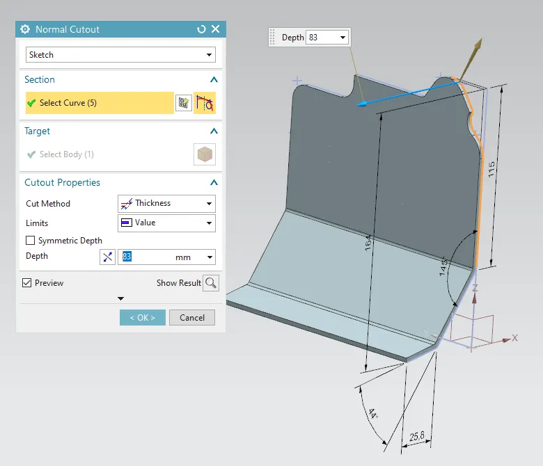
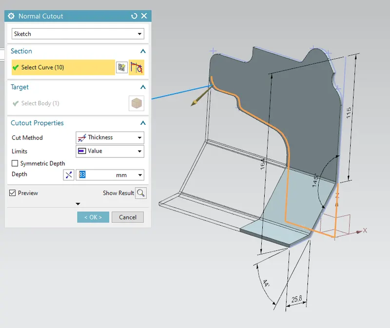
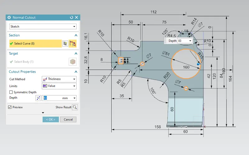
- Unbend: It is used to unbend the bend profiles. unbend and repeat Normal Cutout
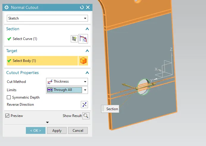
- Rebend : used ro rebend the unbended portions.
- Breaking Corners: It is used to make round corners instead of sharp ones
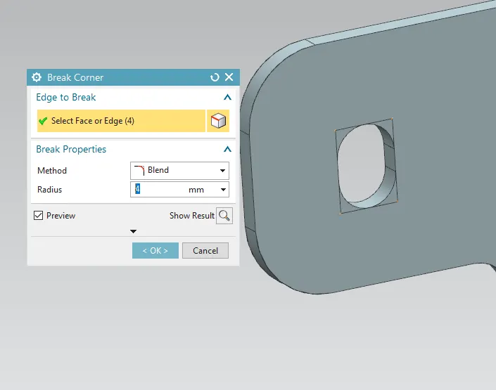
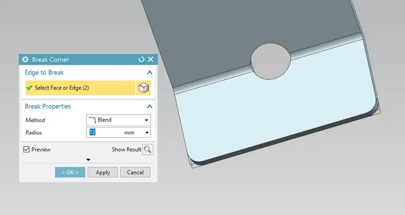
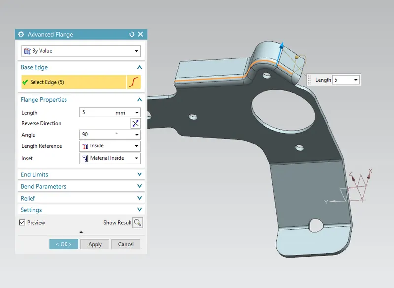
- Advance Flange: Used create flanges for the curved profiles(peofile should be smooth no sharp corners)
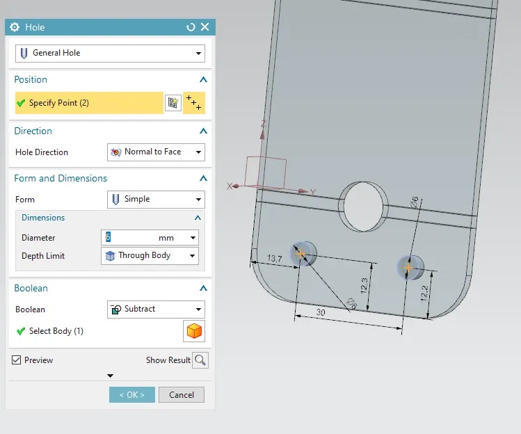
- Unbend the bend profiles and create holes using Hole feature as shown below
Lets create a normal cutout for a profile again as per DWG
- Rebend : used ro rebend the unbended portions.
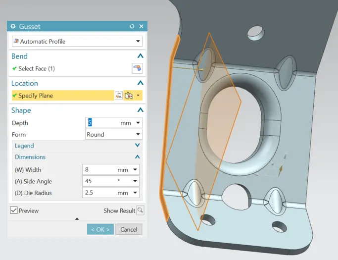
- Gusset: Used for strengthening of the sheet metal between two flanges/Tabs.
Creating 4 Gussets here in the bend portion
- Flat Pattern: It is used to make the sheet metal into a flat pattern for manufacturing.
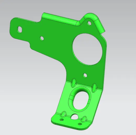
MODEL VIEWS :
ISOMETRIC VIEW :
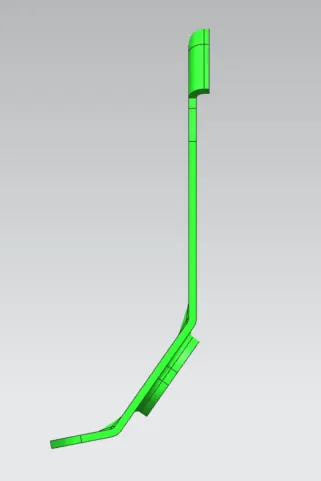
SIDE VIEW :
TOP VIEW :
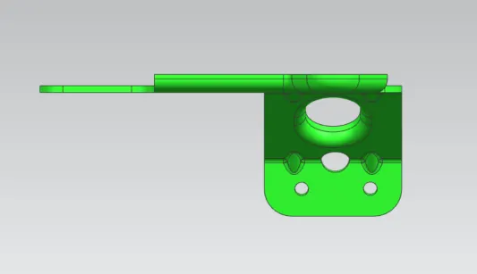
FRONT VIEW :
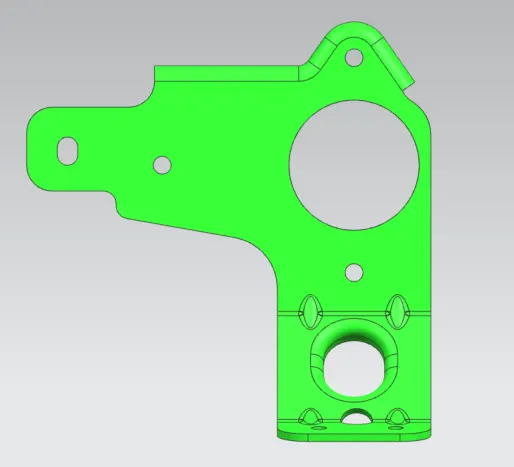
CONCLUSION :
Metal Bracket-II is created as per given Drawing using NX Software.