Advanced Sheet Metal Design Using NX Cad Challenge_1_Casing Design
CASING DESIGN
OBJECTIVE
Write a detailed report on Sheet Metal Component with good explanation on Sheet Metal modelling tools applied throughout the modelling. Also attach the Final model Images (Min. 4 images) of Sheet Metal Casing.
INTRODUCTION
Sheet metal is one of the most versatile materials in the manufacturing industry. It’s made from steel, aluminum, brass, copper, tin, nickel, titanium, or precious metals. It ranges in thickness from wispy leaf through light foil to heavy plate. It takes a variety of forms: plain flat sheets, embossed, etched, ribbed, corrugated, and perforated. And its uses expand across many different industries including transportation, aerospace, appliance manufacturing, consumer electronics, industrial furniture, machinery, and more.
Sheet metal design software considers the fabrication methods needed for manufacturing. As you create flanges and add bends, the sheet metal design software will accurately represent the flat pattern required. The flat pattern can be used to document and manufacture associatively as the design changes.
Here in this project we are dealing with the Sheet metal designing using the software Siemens Nx cad
DESIGN METHODOLOGY
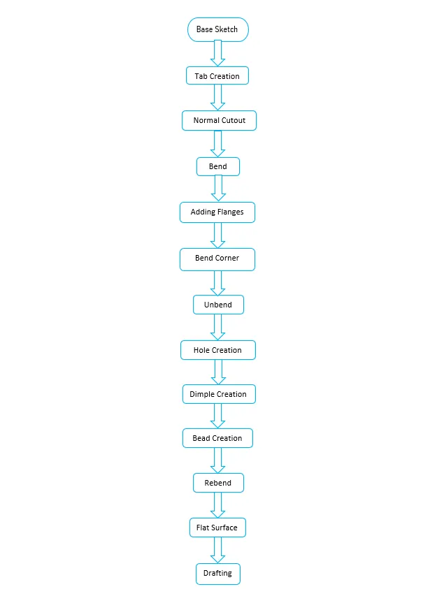
The casing designed for this project consists of features like cut-outs, bends, flanges, holes, dimples, and beads. Every feature is designed in an order following the industrial procedure to keep the design intent. The design methodology used for this project can be summarized as depicted in the flowchart below:
FEATURES USED:
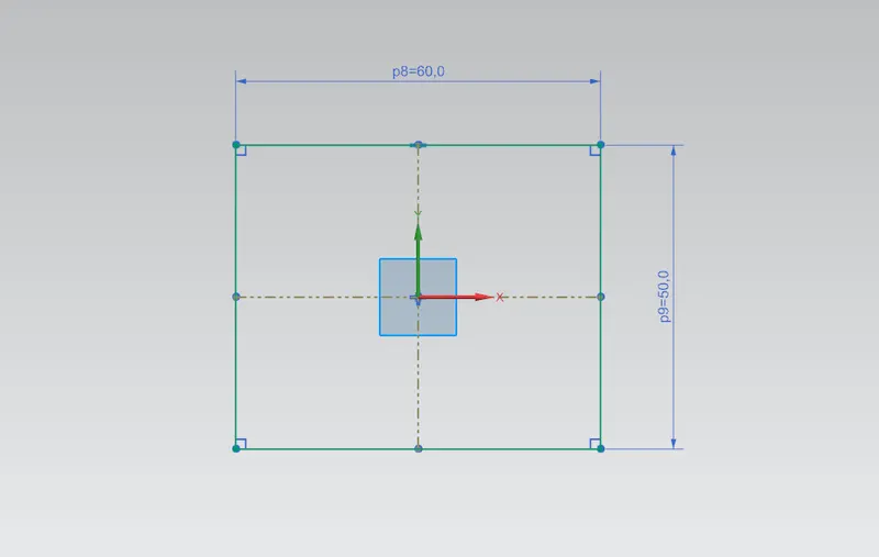
- SKETCH: This is used to create a basic sketch of the design on selecting the desired plane, then later it can be modeled for the requirement.
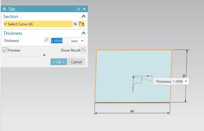
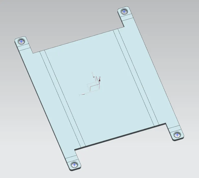
- TAB: This feature is used to create a base tab on selecting the curve drawn in sketch mode as shown below with the appropriate thickness on our desire and it can easily convert that sketch into the sheet metal
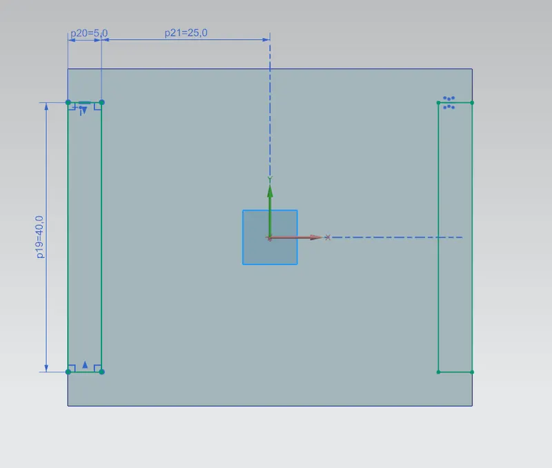
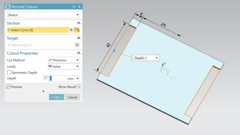
- NORMAL CUTOUT: This feature is used to cut the portions of the sheet metal by selecting the sketch curves drawn.
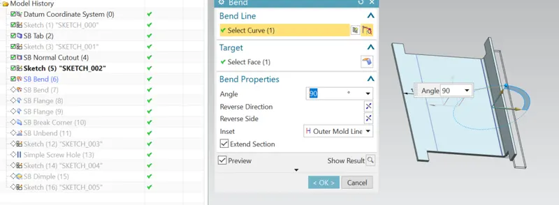
- BEND: This feature is used to bend the sheet metal along the sketched curve upon our requirement.
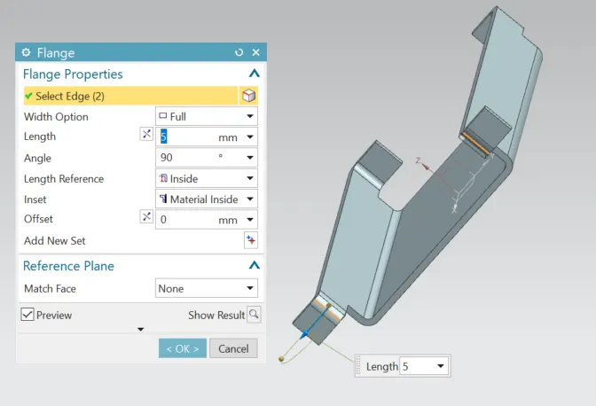
- FLANGE: Flange is used to add flanges on selecting the edges of our sheet metal.
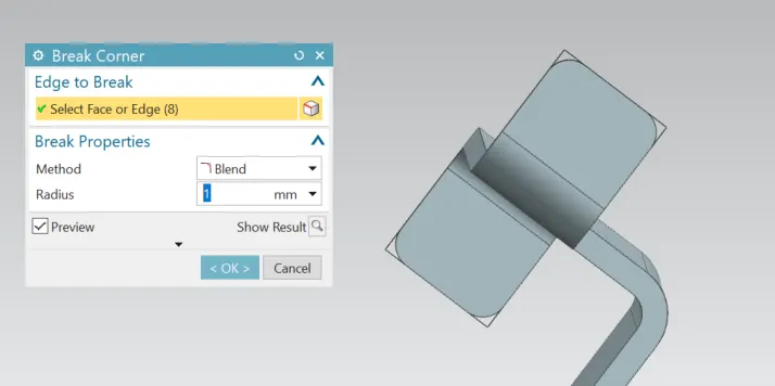
- BREAK CORNERS: Break corners are used to make the edges round for easy handling when using.
- UNBEND: Unbend is a feature used to analyze the model whether a part was perfectly assigned the features, which ensures for a modeler to do further operations on it.
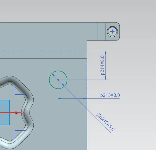
- HOLE: It is actually used for making the holes on the requirement for further assembly of the part by assigning different types of specifications of screws.
- DIMPLE: It is used to draw a dimple on selecting a curve for modeling the sheet.
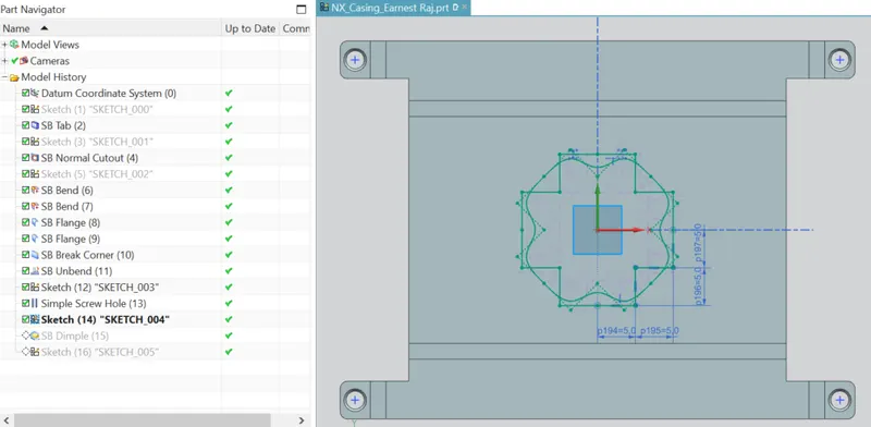
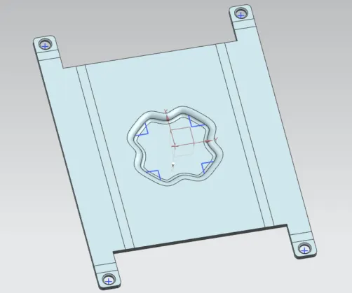
- BEADS: This feature is used to create a bead on the sheet which generally strengthens it.
- After mirroring the feature that is bead feature the model looks as shown below
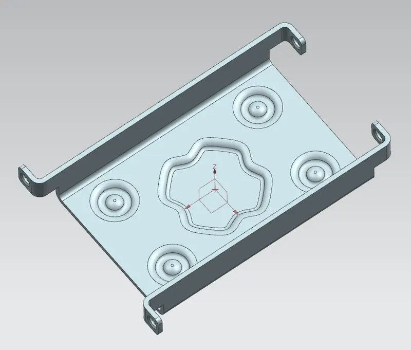
- REBEND: This is used to re-bend the object after all conformations and ready for production.
- FLAT PATTERN: Flat pattern feature allows us to covert 3D sheet metal component into 2D form in Siemens NX software. By using this flat pattern feature we can easily avoid error like interference or collision.
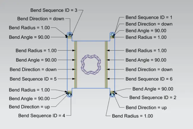
- DRAFTING: It is used to provide the dimensions and views of the designed part to the manufacturing team.
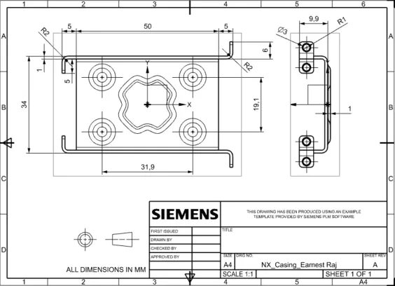
Different views of the model are as follows :
Isometric view:
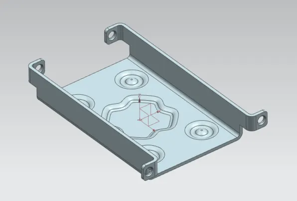
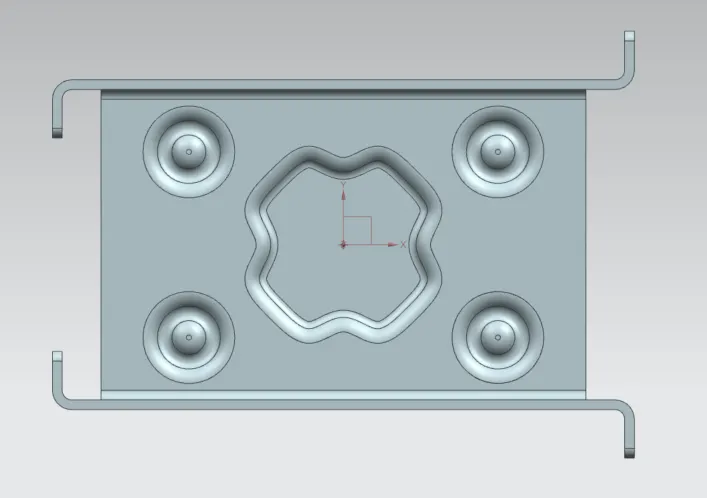
Top view:
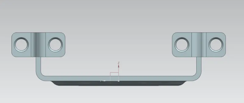
Side view:
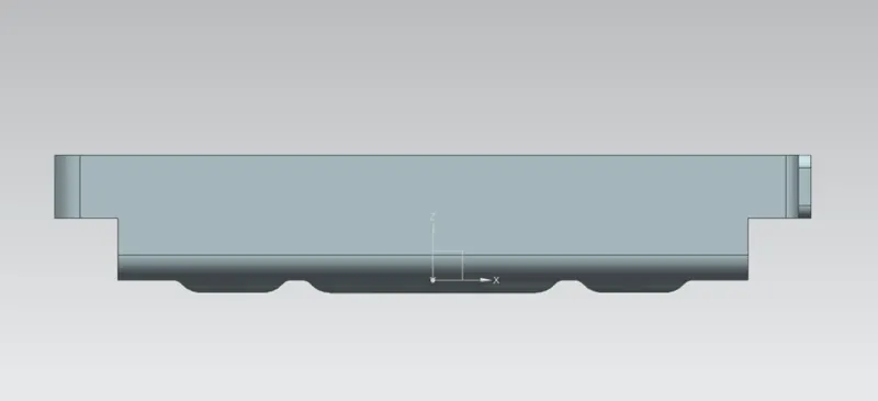
Front view:
CONCLUSION:
- Successfully learnt to design a sheet metal casing in industrial manner by using Siemens NX.