Week 8 - Challenge 2 - Base Bracket Design
CREATION OF BASE BRACKET PLASTIC COMPONENT MODEL FROM CLASS A SURFACE IN CATIA
From the given class A surface a plastic component model is to be created with a thickness of 2.5mm and draft angle of 3 degrees.
- Checking class A surface for gaps.
The Provided class A surface should be checked for any discontinuities by using boundary command. If any gaps are present then the surface should be modified.
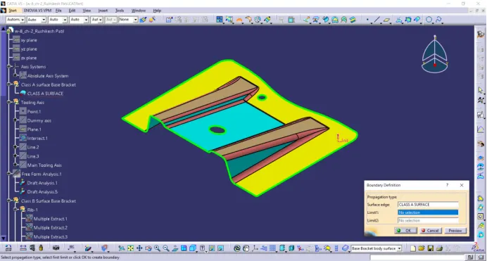
In the above figure we can observe there are no gaps in the surface.
- Visually inspect the surface for possible direction of tooling axis.
Note: The Tooling axis (The Axis along which the core and or cavity move for part creation) should be in such a direction so that it would use minimum or no side core for the preparation of part.
In X-direction:
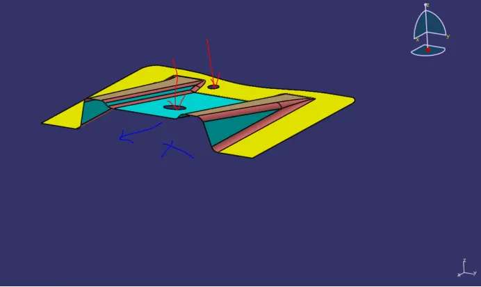
Along X-direction there is a need of side cores for the 2 holes shown above.
In Y-direction:
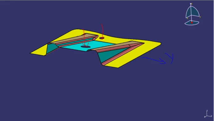
Same as along Y there is a need of side cores hence Y-direction is also unfit.
In Z-direction:
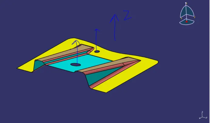
Tooling axis along Z-direction fits as there is no need of any side cores for the holes.
- Creating a dummy axis along Z-direction:
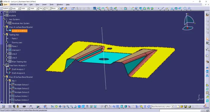
- Creating Tooling axis:
From visual observations along X direction there will be no problem as the surfaces are properly drafted and can be seen visually. In Y-direction we can observe two surfaces which are unsure for tooling. Intersect lines parallel to the yz plane and passing through the center of hole as shown below
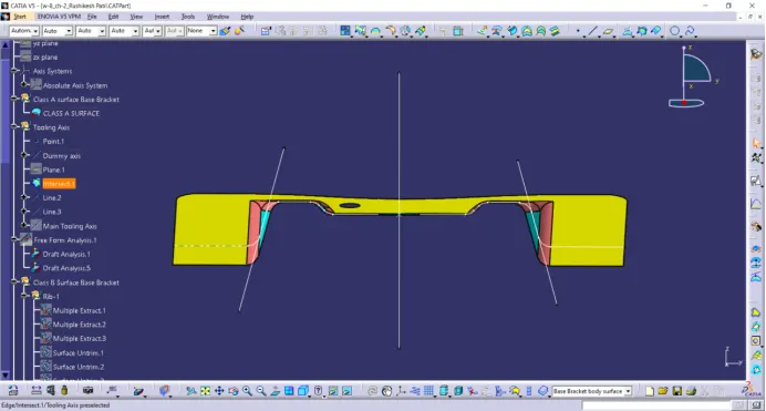
Create two lines as shown above passing through the surfaces which are unsure.
Create a line bisecting the two lines as shown below.
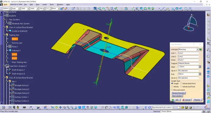
This axis will be main tooling axis of the Class A Surface since it is clear in x-direction.
Change the colour of tooling axis to green.
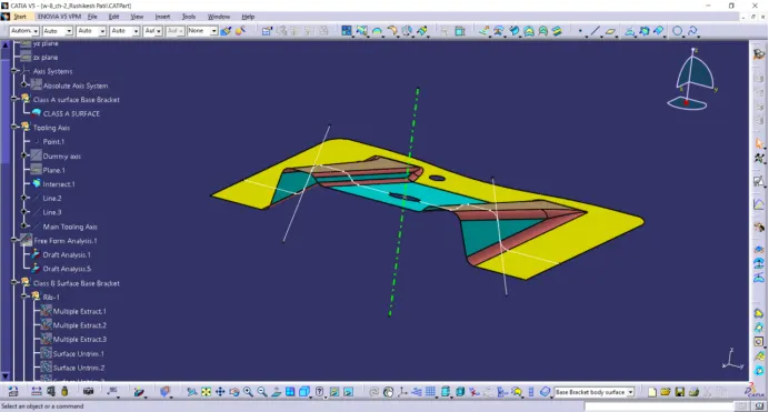
Note:
Bisecting method: Here bisecting method is used for the creation of tooling axis because it will provide exact center line of the drafts on surface.
- Draft Analysis of Class A Surface
Click on the feature draft analysis in Analysis tab
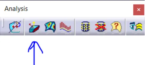
or Go to insert >Analysis > Feature Draft Analysis
Click on the compass in direction row and align the compass along the tooling axis as shown below. Also disable the analysis under running point option in display row in draft analysis tab.
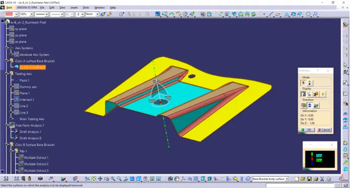
Some times the compass disappears or will be placed far fron the surface, zoom out from the surface and disable and enable the compass to see the compass and drag it to the tooling axis.
Once the compass is aligned lock the compass.
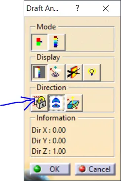
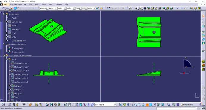
After locking left click anywhere on the surface. It will look as shown below.
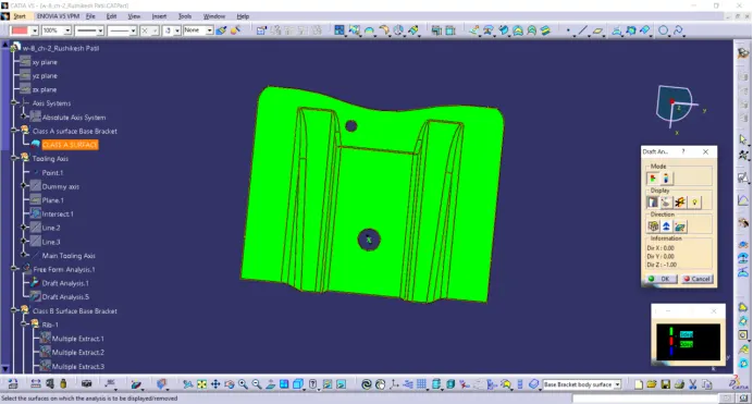
The green colour on the surface shows that the entire surface is provided with a minimum draft of 3 degrees.
If any surface shows blue colour then the surface should be modified because it has a draft angle below 0 degrees along tooling axis.
The Class A Surface is clear to proceed further for part creation.
- Creating Class B Surface:
For creating Class B Surface the Class A is surface is divided into following parts:
- Rib-1
- Rib-2
- Slant rim
- Main base
- Fillets
Rib-1:
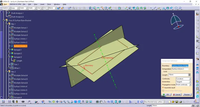
Extract the surfaces of left rib of class A surface as shown below ignoring the fillets.
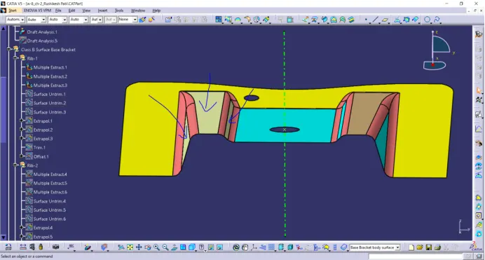
Untrim the extracted surfaces.
Extrapolate the untrimmed surfaces to 10mm following the curvature of surfaces in all directions.
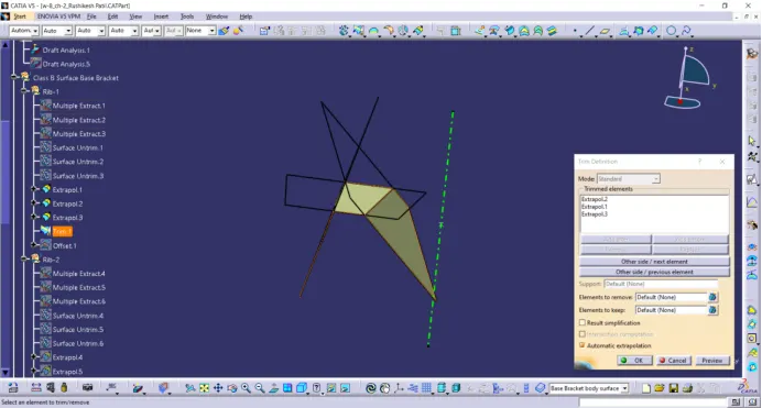
Trim the three surfaces as such of Class A surface
Offset the trimmed surface to 2.5 mm downwards.
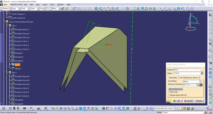
Thus Rib-1 of class B Surface is created.
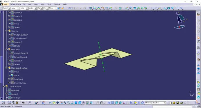
Following the same steps of Rib-1 the other parts like RRib-2, Slant rim and Main base are created accordingly as shown below
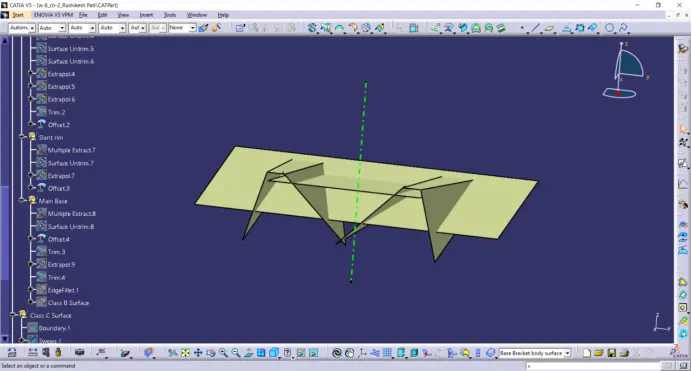
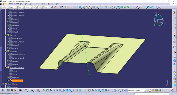
All the surfaces are trimmed to create a class B surface as shown below
Fillets in Class A surface are measured using measuring tools and fillets are applied on class B surface adding the thickness of part to the radius as the class B surface is a offset to class A surface below so the thickness is added to the fillet radius to provide a uniform thickened plastic part.
- Creating Class C Surface.
Create a outer boundary of class A surface using boundary command and sweep the boundary with draft direction giving the direction of tooling axis and the draft sholud be of 3 degrees facing outward down to class A boundary.
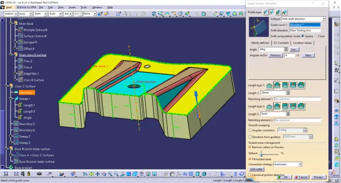
Repeat the same procedure for the inner two circles but the sweep should be inwards down to circular boundary.
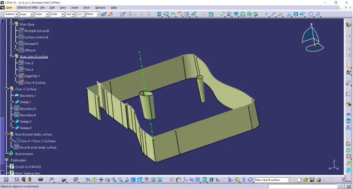
Thus Class C surface is created.
- Join class A surface and class C surface and trim it with class B surface to create a closed hollow surface of base bracket part with 2.5mm thickness.
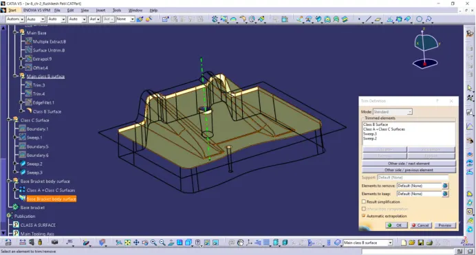
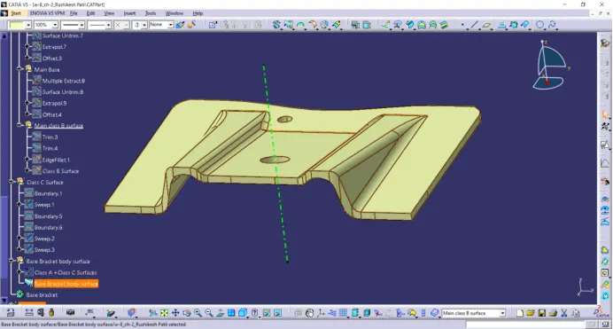
Also check the created surface for any gaps using boundary command. If gaps are not present it will through a message showing no boundaries.
If there are any gaps it should be modified.
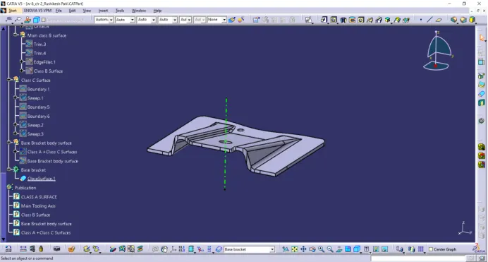
- Part body creation.
Go to the Part design and use close surface command to convert the closed base bracket surface into body of 2.5mm thickness.
- Draft analysis on Base bracket body.
Go to feature draft analysis and align the compass to the tooling axis and left click on the surface as shown below.
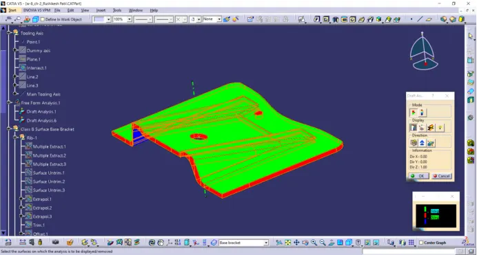
We can observe there some red colour on the class C surface it is because the the draft angle of class C surface is in between 0 to 3 degrees. (Class C surface is created with draft angle of 3 degrees)
Check the draft angle of class C Surface using analysis under running point and find the minimum draft along the red colour surface.
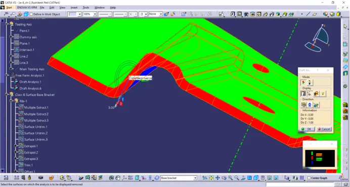
We find the minimum draft angle to be 2.6 degrees so change the upper limit of the draft angle scale to 2.5 degrees.
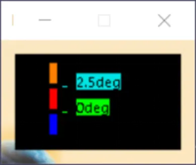
Now the entire part will pass the draft analysis making the minimum draft to be 2.5 degrees.
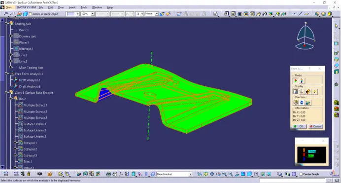
We can observe blue surface on class B surface it is because the compass is opposite direction to its tooling axis once we invert the compass we can check the draft for class B surface also as shown below.
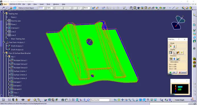
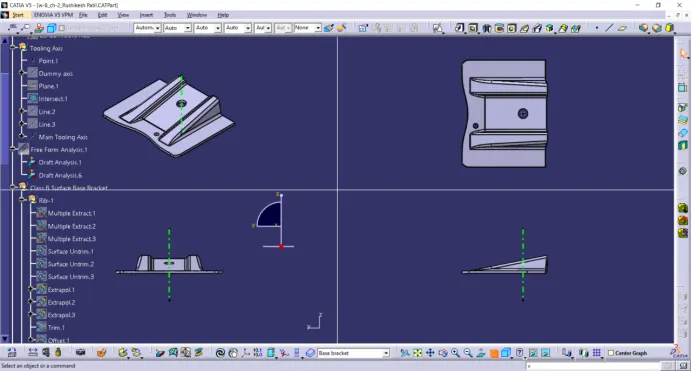
Various Orientations of Base Bracket:
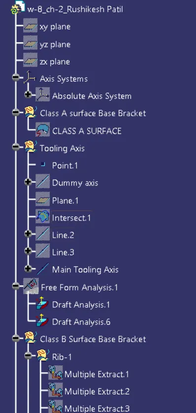
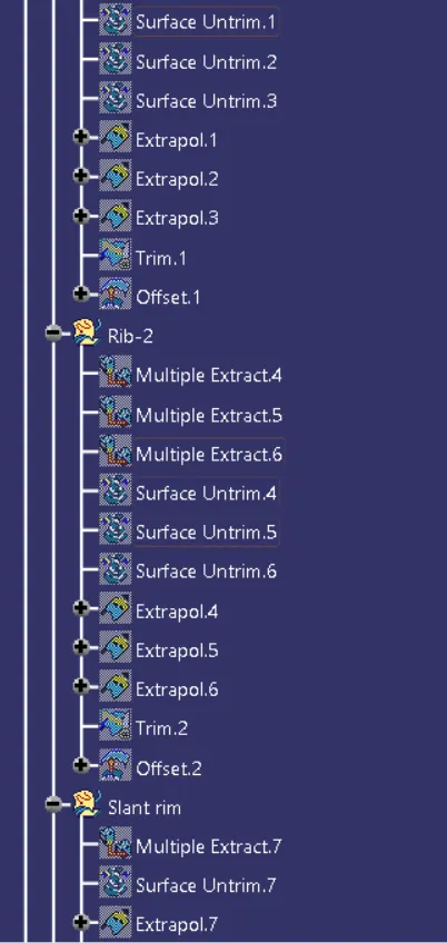
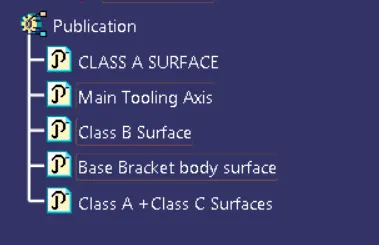
Tree Structure: