Week 8 - Challenge 1 - Draft Analysis on a Fan Cover
DRAFT ANALYSIS ON FAN COVER IN CATIA
Draft Analysis:
Draft analysis is a technique used to analyze whether our part model created in cad is manufacturable based on the draft condition applied.
No parts can be ejected from the tool if it is having a 0 degree profile with the dirction of toolin axis of part. It will provide more friction along the contact between part and mold which can create damage to the part while removing so that the parts are provided with a minimum draft for easy ejection of part from mold.
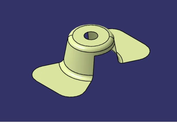
Here we are performing draft analysis on Class A surface of fan cover.
Steps for draft analysis:
- Check the surface for any gaps.
We can check the gaps by clicking on boundary command and selecting the class A Surface. If there are any gaps in the middle of surface it will be displayed in green colour.
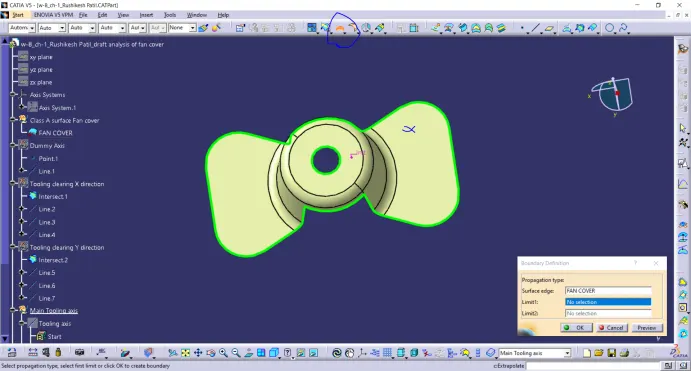
In the above figure we can obsreve there are no gaps in the surface.
- Visually inspect the surface for possible direction of tooling axis.
Note: The Tooling axis (The Axis along which the core and or cavity move for part creation) should be in such a direction so that it would use minimum or no side core for the preaparation of part.
Inspection in X-direction:
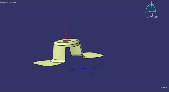
We can see in above picture that if the tooling axis is along X-direction we need to provide a side core for the hole so X-direction is invalid for the part.
Inspection along Y-direction:
Along Y-direction also we need to provide a side core so it is also not valid.
Inspection along Z-direction:
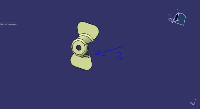
We can see that along Z-direction there is no need for a side core so along Z will be our Tooling axis.
- Creating a dummy Axis along Z direction.
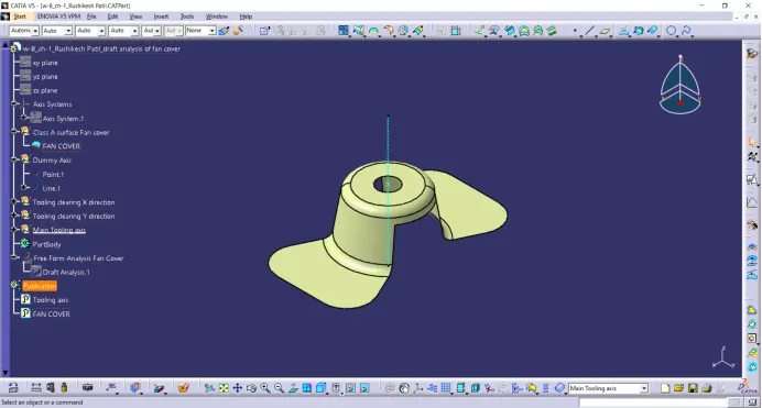
- Tooling clearance in X-direction.
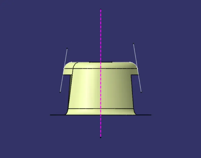
Create a intersection line Parallel to XZ plane passing through the dummy axis point on the class A surface. Then create lines along the direction which we visually doubt about having draft.
Note: Surfaces perpendicular to the tooling axis will always get cleared.
Then create a line along Z, bisecting the two lines with doubt of draft as shown below and name the line as axis clearing X-direction.
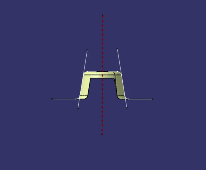
- Tooling clearance in Y-direction.
Repeat the same steps used in clearing X-direction with using intersection lines parallel to YZ plane.
- Creating main Tooling axis.
Create a line bisecting both the axis clearing X-direction and Y-direction along Z-direction passing through the center of class A surface. This will be the Tooling axis for the surface.
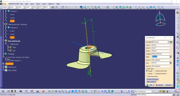
Note:
Bisecting method: Here bisecting method is used for the creation of tooling axis because it will provide exact center line of the drafts on surface.
- Draft analysis
Click on the feature draft analysis in Analysis tab.
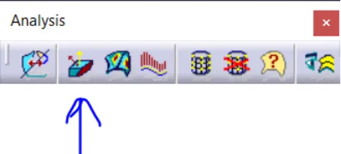
Click on the compass in direction row and align the compass along the tooling axis as shown below. Also disable the analysis under running point option in display row in draft analysis tab.
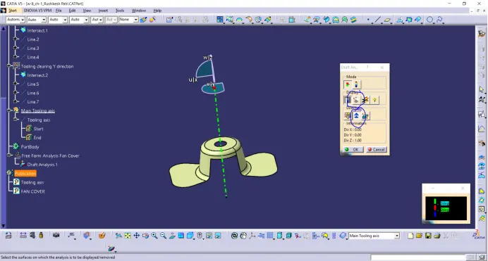
Some times the compass disappears or will be placed far fron the surface, zoom out from the surface and disable and enable the compass to see the compass and drag it to the tooling axis.
Once the compass is aligned lock the compass.
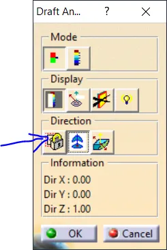
After locking left click anywhere on the surface. It will look as shown below.
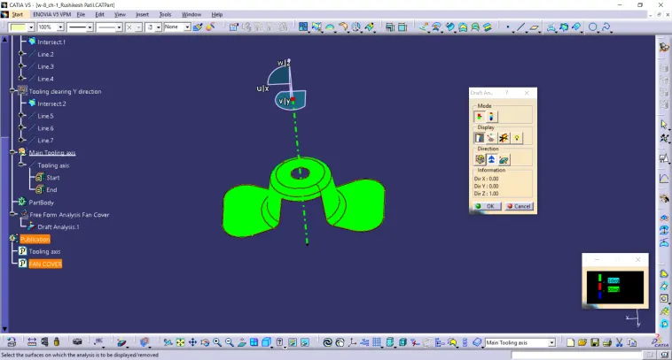
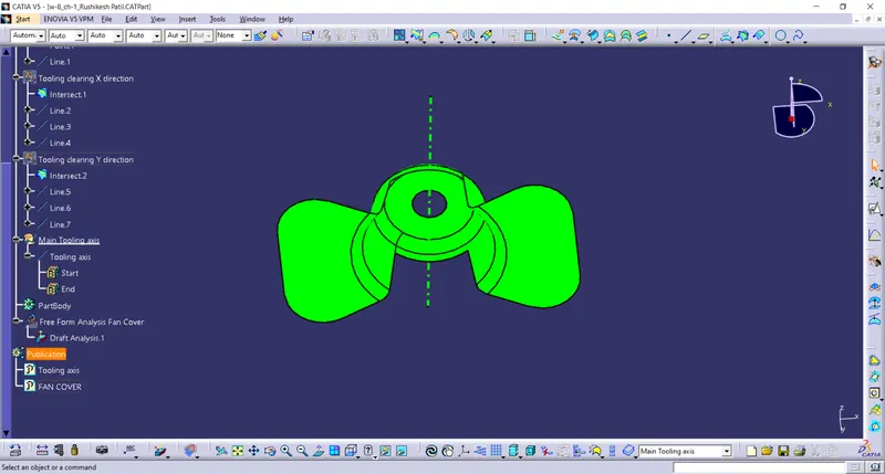
The green colour on the suface shows that the entire suface is provided with a minimum draft of 3 degrees.
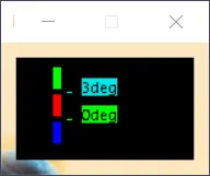
We can see a tab showing the range of draft we can modify the range acoordingly by double left clicking on the range values in bottom right tab.
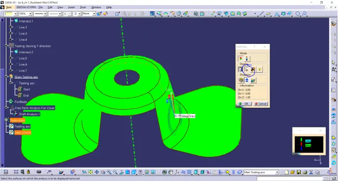
We can also find the draft angles at required points using analysis under running point.
Placing the cursor on surface will give the draft angle at that points surface as shown below.
We can also reverse the compass direction by clicking the inverse draft direction in as shown below
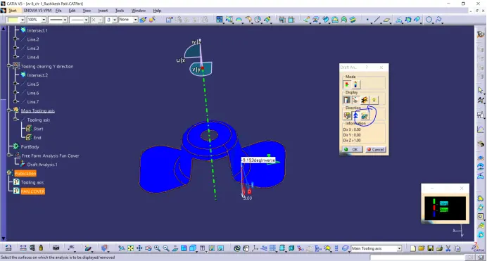
Here the blue colour indicates that the draft angle in below 0 degrees with the compass direction.
If any surface is in red colour it indicates that the draft angle is between upper and lower limits of draft.
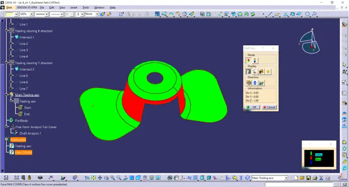
Here I have changed the upperlimit to 10 degrees so the red colour is indication that the surface lies in between upper and lower limits of draft angle.
We can also play along with the range of drafts by changing the scale as shown below
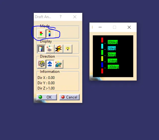
We can also change the values in the range.
Thus draft analysis is made on Fan Cover Class A Surface.
Various orientations of draft analysed fan cover:
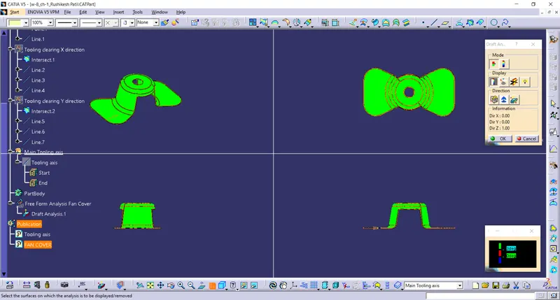
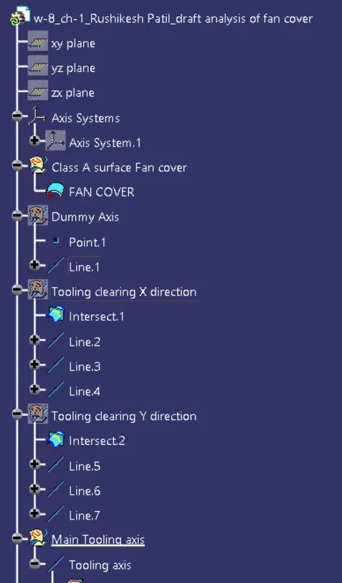
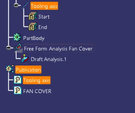
Tree structure: