Week 8 - Challenge 3 - Switch Bezel Design
CREATION OF SWITCH BEZEL PLASTIC COMPONENT MODEL FROM CLASS A SURFACE IN CATIA
From the given class A surface a plastic component model is to be created with a thickness of 2.5mm and draft angle of 3 degrees.
- Checking class A surface for gaps.
The Provided class A surface should be checked for any discontinuities by using boundary command. If any gaps are present then the surface should be modified.
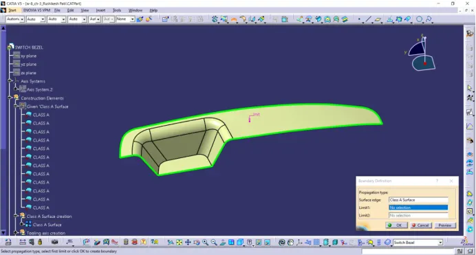
The given class A surface is joined together to form a single surface and gaps should be checked. If gaps are formed the surface should be modified.
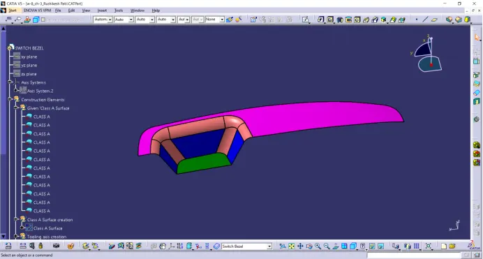
Given Class A Surface:
Joined Class A Surface:
- Visually inspect the surface for possible direction of tooling axis.
Note: The Tooling axis (The Axis along which the core and or cavity move for part creation) should be in such a direction so that it would use minimum or no side core for the preparation of part.
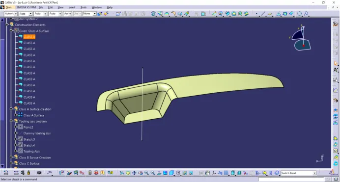
From visual inspection the tooling direction should fit along z direction and through the center of base of switch bezel.
Dummy Tooling Axis:
- Creating Tooling axis:
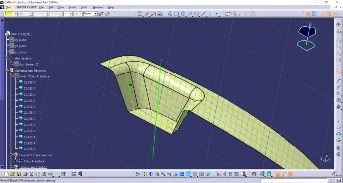
Create an axis system at the center of base surface and along YZ plane create a positioned sketch as shown below:
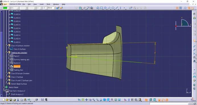
Along XZ plane create a positioned sketch as shown below:
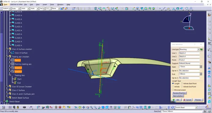
Create a line bisecting those two sketches and through the center point of base surface of switch bezel as shown below:
Note:
Bisecting method: Here bisecting method is used for the creation of tooling axis because it will provide exact center line of the drafts on surface.
- Draft Analysis of Class A Surface
Click on the feature draft analysis in Analysis tab
Go to insert >Analysis > Feature Draft Analysis
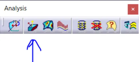
Click on the compass in direction row and align the compass along the tooling axis as shown below. Also disable the analysis under running point option in display row in draft analysis tab.
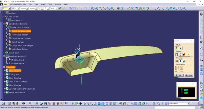
Some times the compass disappears or will be placed far from the surface, zoom out from the surface and disable and enable the compass to see the compass and drag it to the tooling axis.
Once the compass is aligned lock the compass.
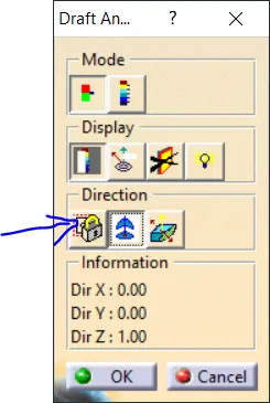
After locking left click anywhere on the surface. It will look as shown below.
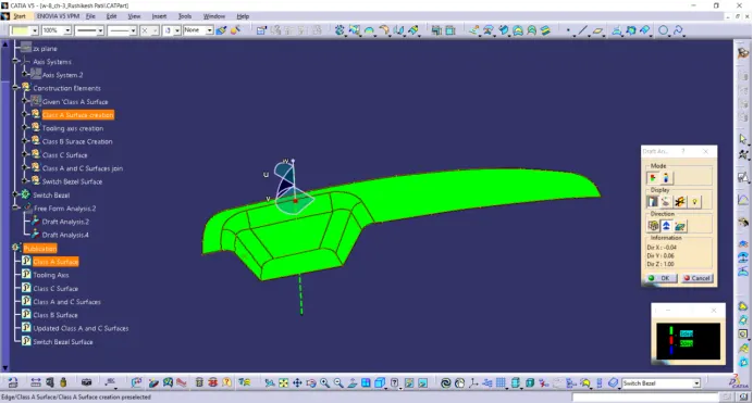
The green colour on the surface shows that the entire surface is provided with a minimum draft of 3 degrees.
If any surface shows blue colour then the surface should be modified because it has a draft angle below 0 degrees along tooling axis.
The Class A Surface is clear to proceed further for part creation.
- Creating Class B Surface:
For creating Class B Surface the Class A is surface is divided into following parts:
- Switch Bezel base
- Side walls
- base
- Fillets
Switch Bezel Base:
Extract the surface from class A Surface as shown below:
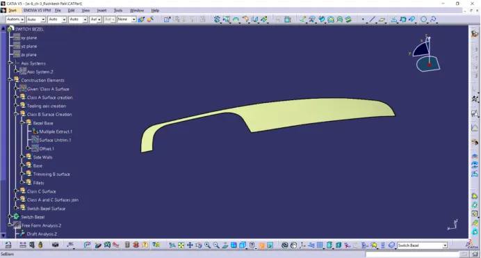
Untrim the extracted surface.
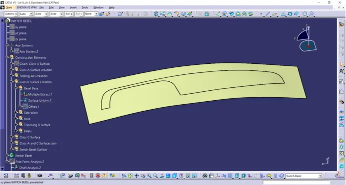
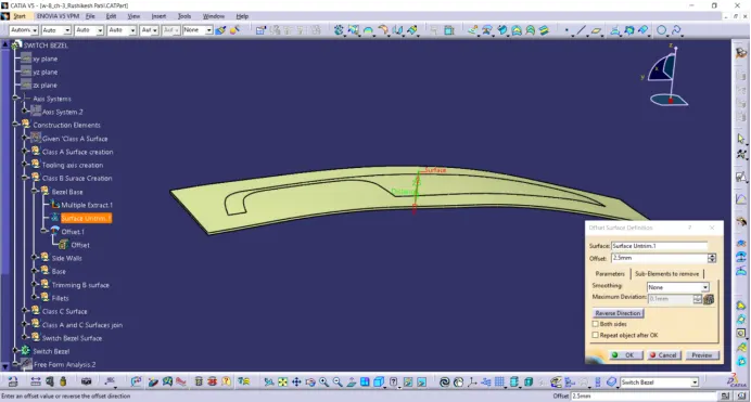
Offset the untrimmed surface to 2.5mm below.
Repeat the same steps for other surfaces as shown below
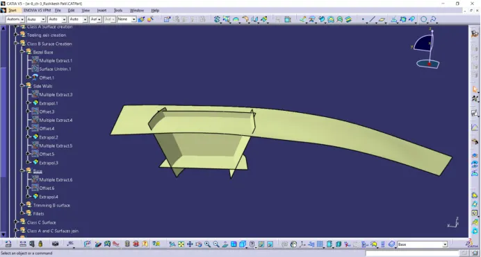
Make sure that the surfaces are in contact if not extrapolate the surfaces as shown above.
Trim all the surfaces to form the class B surface without fillets as shown below
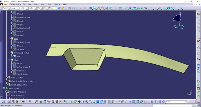
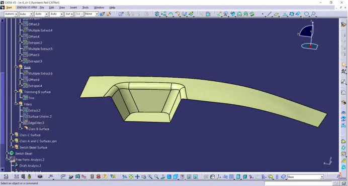
Apply fillets wherever necessary by measuring the class A surface fillets radii and use the measurements according to the offset such that the thickness of 2.5mm should be maintained class A and class B surfaces.
- Creating Class C Surface.
Create a outer boundary of class A surface using boundary command. As the boundary is not tangent and perpendicular breaks are there the boundary is splitted into multiple parts and sweeped along the tooling axis with a draft of 3 degrees.
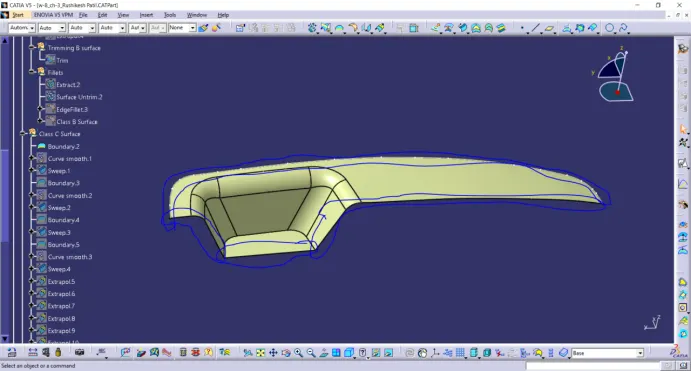
The curves extracted are smooth curved using curvature and sweeped to avoid any irregularities as shown below
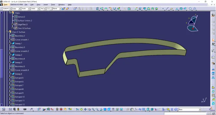
The irregularities at the edges are cleared by extrapolating the edges and trimming together to form class C surface
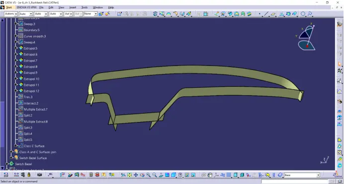
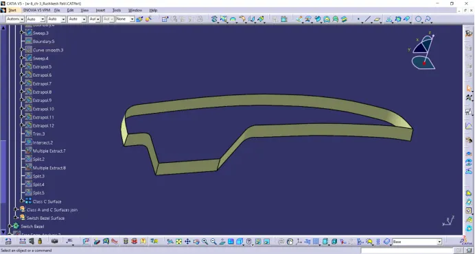
If trim is not possible split the extrapolated surface along the intersection of surfaces and join together.
- Join Class A and Class C surfaces.
While joining the two surfaces we got gaps between surfaces. To cover the join, the class A and C surfaces are extrapolated to 0.1mm along the joining part so that the gaps between the join are removed. This step is followed only after findings gaps on applying maximum of 0.003mm of merging distance.
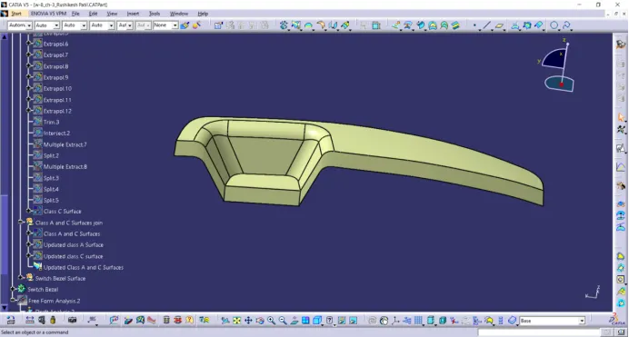
- Trim the joined class A and C surfaces with class B surface.
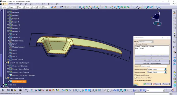
Also check the created surface for any gaps using boundary command. If gaps are not present it will through a message showing no boundaries.
If there are any gaps it should be modified.
- Part body creation.
Go to the Part design and use close surface command to convert the closed base bracket surface into body of 2.5mm thickness.
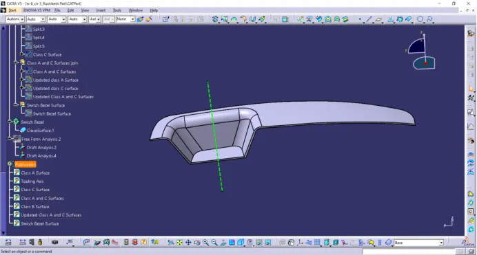
- Draft analysis on Switch Bezel
Go to feature draft analysis and align the compass to the tooling axis and left click on the surface as shown below.
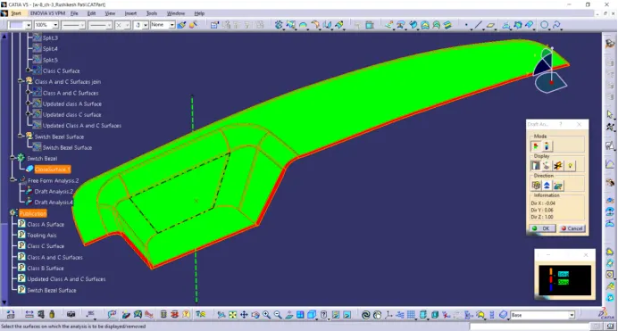
We can observe there some red colour on the class C surface it is because the the draft angle of class C surface is in between 0 to 3 degrees. (Class C surface is created with draft angle of 3 degrees). Change the upper limit to 2.9 degrees and we get a complete green colour on the thickness walls also.
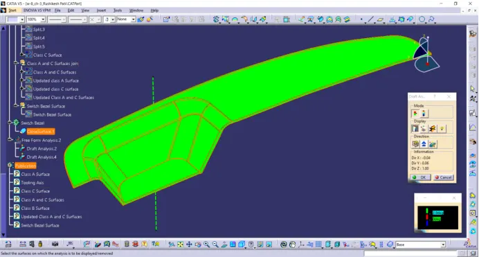
We can observe blue surface on class B surface it is because the compass is opposite direction to its tooling axis once we invert the compass we can check the draft for class B surface.
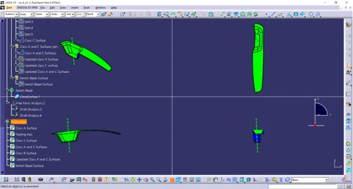
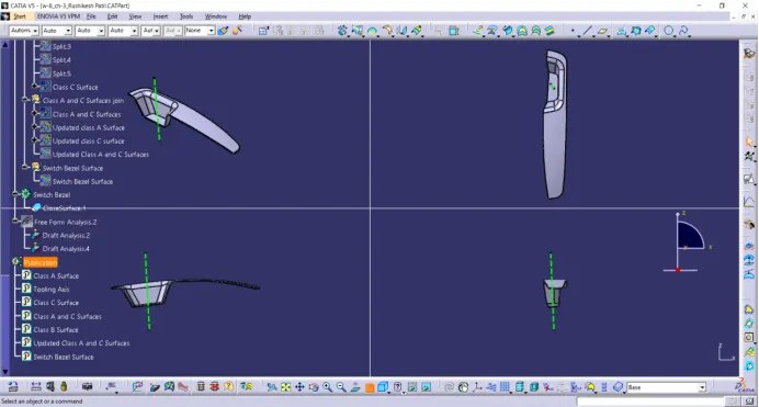
Various Orientations of Switch Bezel:
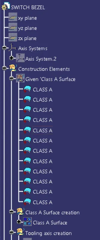
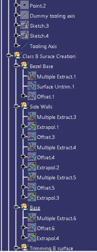
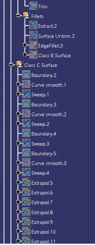
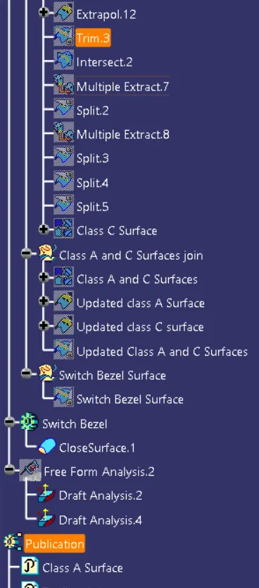
Tree Structure: