Photo Realistic Rendering
MODELLING OF AMERICAN CHOPPER IN SOLIDWORKS
Introduction
Solidworks360 is 3D designing software which is cable of different function, to create a 3D model of our liking. In this Software there are lot of features to make our model look realistic we use Rendering Features. As being a multi platform for our creation of American Chopper model we use this Software for creating model.
In this project we learn about the design of American chopper assembly with help of SOLIDWORKS. In this we first learn to use the commands and then we draw parts. By using blueprint sketch, we get idea of sketching the parts and its dimensions. After designing all the parts we do assembly of chopper. After assembly we add decals, lights, camera and do rendering of chopper by using SOLIDWORK visualization.
The components which we learn in chopper are:-
- Chassis
- Engine with exhaust system.
- Front wheel and rear wheel with rims and sprocket calipers.
- Front Fork
- Front and rear fender
- Oil tank
- Chain and transmission belt
- Kickstand and foot pedal
While creating this model we undergo part design and Assembly of all these parts and rendering the created Assembly by rendering tools to give a realistic touch to our model by using the Software Solidworks360 and SOLIDWORKS Visualize.
Objective
- To learn the basic commands of SOLIDWORKS.
- With the help of blueprint sketch we design all the parts of chopper.
- Assembling all the parts in SOLIDWORKS.
- Get the knowledge of concepts like decals, light and camera angle. 2
- Proper setting of image quality and getting realistic view with the help of Photoview 360.
- Rendering of American chopper has done with help of Solidworks visualization software
Design Approach
There are two types of approach in design procedure.
- Bottom up approach and
- Top down approach.
Here in this project we have used Bottom-up approach, we get clear idea by defining these terms.
Bottom up approach: The design approach in which the most primary operations are specified first then combined it later to make larger progressive unit.
Top down approach: Top down assembly modelling is an assembly-centrist modelling method where the assembly design is started at the highest level possible, and individual parts and sub-assemblies are defined within the context of the overall assembly.
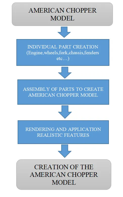
CREATION OF PARTS AND ASSEMBLY OF THE AMERICAN CHOPPER
In the creation of parts of American Chopper model the first step is to create the different parts of the American Chopper by using Solidworks360. Before creating the different parts we have to know the different tools and features which are Available for the part creation of the project. We have listed some different tools and features ,surface features etc are listed below. Which we have used for the part creation:
SKETCH TOOLS :
Sketch:
In the sketch tool bar, there is a sketch icon which allows us to create a 2D sketch on the selected plane or selected surface or selected point.
Line:
Line tool is used to create a line between any two points and from this tool we can create different types of line like Construction Line ,Midpoint line etc.
Rectangle:
This tool is used to create a rectangle in the sketch plane and we can draw the rectangle in different ways like center point, by sides, by diagonal lengths ,three point rectangle and parallelogram.
Slot:
This tool is used to create slot which is created by using the center the distance and radius of the slots and there are other options for creating arc slot also.
Circle:
This tool is used to create a circle by using the radius length and there is an other option for the creation perimeter circle.
Arc:
This tool is used to create a arc by the radius and also by using the sides and also by use three points.
Polygon:
This tool is used to crate a polygon by defining the inner circle and the no of side and the angle between the sides in the sketch plane.
Spline:
This tool is used to create a curve driven by points between any two points are surfaces and we can create the curve without any uniformity.
Ellipse:
This tool is used to create a ellipse based on the major and minor radius and in this tool they are other optio9ns where we can create half ellipse etc.
Sketch Fillet:
This tool is used to create rounded corners called as fillet by selecting the corners or the intersection of lines and by entering the radius values.
Sketch Chamfer:
This tool is used to create inclined edges by slecting the angles and the distances at the required lines on the sketch.
Point :
This tool is created to create a point on the sketch palne to create a reference for our diagram as required applications.
Trim entities:
This tool is used to trim or to cut the entities which are intersecting and unwanted lines by selecting By using power trim in the sketch plane.
Convert entities:
This tool is used to concert the boundaries of any 3D boundary in to lines for which we can take as reference for creating the sketch .
Extend entities:
This tool is used to extend any line or arc to other line meeting arc by selecting extending entity and the boundary of the entity.
Mirror entities:
This tool is used to mirror the sketch by selecting the mirroring entities and after that selecting the line with which respective they have to mirrored
Offset entities:
This tool is used to offset the required entities or sketch part or sketch lines to be copied inward or out ward of the slected entities to the required distances.
Linear Sketch pattern:
This tool is used to create a copy of the sketch in form of a pateern in linear fashion along the selected direction in the sketch.
Circular sketch pattern:
This tool is used to create a copy of sketch in circular pattern at an equal intervals of angles in the sketch plane.
3D FEATURES :
Extrude Bose/Base:
This is a tool used to convert a 2D closed sketch to a 3D solid by giving the height distance of extrude.
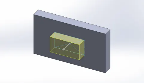
Revolve Bose/Base:
This tool is used to create a revolved solid by convert a closed sketch and revolving with respective to a axis or plane.
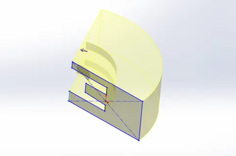
Swept Bose/Base:
This tool is used to create a sweep hollow solid me by creating a closed sketch and creating a closed profile along the curve which is selected.
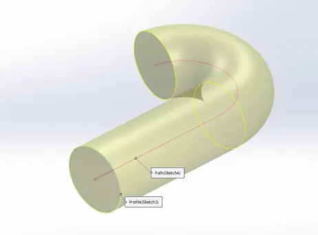
Loft Bose/Base:
This tool is used to create a solid body which has a curve guide through two different closed of two cross section and areas.
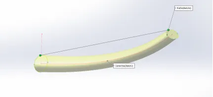
Extrude Cut:
This tool is used to cut or make hole or remove the unwanted surface from a solid body by created a closed profile on the required surface or plane of solid.
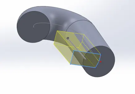
Revolve cut:
This tool is used to cut a closed sketch profile in revolved manner with respective to the given axis or line removing required material from the solid.
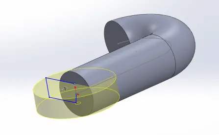
Mirror entities:
This tool is used to create a mirrored solid of the same dimensions with reference to the plane or the surface of the body.
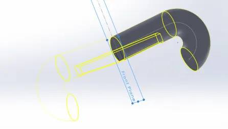
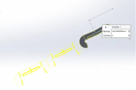
Linear pattern:
This tool is used to create a linear pattern of solid or cut in solid material in a linear fashion by selecting the number copies and the offset distance between the selected body or cut solid.
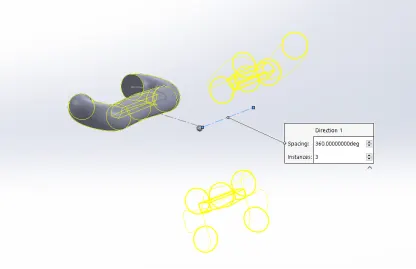
Circular pattern:
This tool is used to create a circular pattern of copies by selecting a reference a circle from which it would create copies at intervals of angles according to the design.
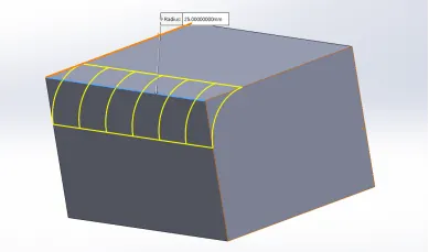
Fillet/Chamfer:
This tool is used to created a rounded surfaces by giving the radius to the selected edges of the solid.
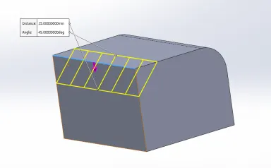
Draft:
This is used to create a chamfer between two different area profile combine by inclined way to create a solid.
Reference plane:
This is used to create a new plane by taking the reference of different points, lines and curves according to the requirement.
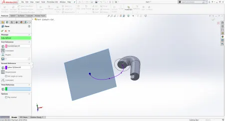
Projection curve:
This is used to create a one single curve which is formed by combining to different curves having a joining points but situated in two different planes resulting in smooth curve passing from both planes.
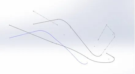
Composite Curve:
This curve is combination of two different projection curve to create a one final composite curve which can pass through the two projection curves
Split:
This is used to remove or split or cut the unwanted parts or solid bodies intersecting each other to result a perfect one solid body.
Combine:
This tool is used to create a combined solid body by two different Solid bodies to get a one body enhanced by the two solids.
SURFACE FEATURES:
Extrude Surface:
This tool is used to create an extruded surface by creating a closed profile in the chosen direction of required thickness.
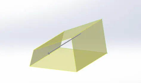
Revolve surface :
This tool is used to create a revolved surface of specified thickness with respective to the axis.
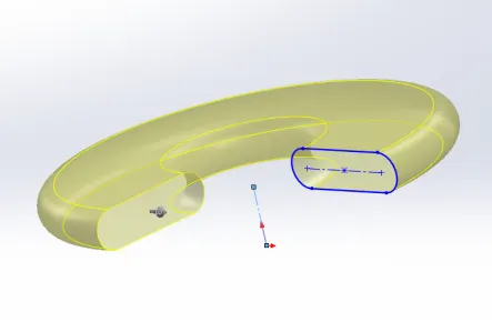
Swept Surface:
This tool is used to create a swept surface along the guided profile or curve with the required thickness of the surface.
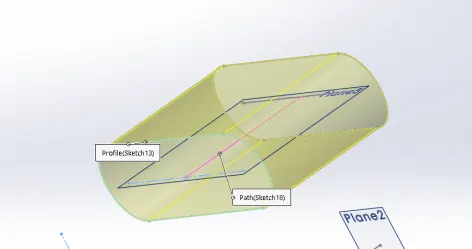
Trim surface :
This tool is used to trim the unwanted surfaces for the profile by selecting the specified surface which is to be removed.
Knit surface:
This tool is used to combine two surface as a single body or surface by knitting and make the both surface boundaries coincident and tangent to one another.
Mirror surfaces:
This tool is used to create a mirrored surface of the same surface with respective to the selected plane and selected Boundary of the surface.
Fillet:
This tool is used to create a rounded corners by selecting edges of the surfaces and giving them the required surfaces.
Boundary surfaces:
This tool is used to create a surface which are connected and going through different boundaries by taking the reference of the edges.
These are the some of the most common tools used in creating our parts required for American chopper. The parts of the American chopper are divided in to 13 parts which are used to create a American Chopper Assembly. There are some of the main points that we have to know first before starting to drawing the model of parts:
- We have to see the units are correctly set to Millimeters ,If no we have to set it by clicking on the Right Hand corner of the workspace.
- The every tool , feature, solid body, appearance and surface we use is updated in the feature tree we can edit and see the feature in this tree
- If we draw any sketch we have to give the perfect dimensions such that the sketch is fully defined other wise it will rearrange itself if accidentally snap those under defined it would change the profile sketch. So we have to be carefully in defining the elements.
- We does not have to Over define the sketch profile such that it will error and we cannot change it to any required solid body. This can be seen in the feature tree beside the sketches solid as symbol ‘-‘(under defined) and ‘+’ for over defined.
- We have to careful in giving the relations between any elements ,in the sketches’ we have to reference it to the origin.(pic of the environment).
By keeping these in mind we began to create the parts of the American chopper as described below:
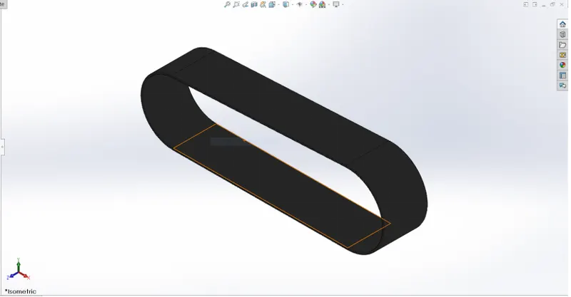
TRANSMISSION BELT:
- The first step is to build a profile of Transmission belt by taking Front Plane as sketch plane by using the sketch tools like:
- Line
- Three point arc
- Offset entities.
- Then by drawing the model we will make the sketch fully constrained exit the sketch and will use the feature called Extrude boss base and give the required width of the transmission belt to get the required belt Model as shown figure.
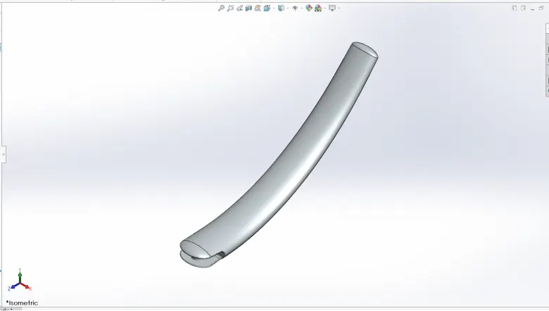
KICKSTAND:
- In this kickstand we will make sketch profile on the front plane and draw an ellipse after sketching we will create a another profile of sweep emerging from the center point of the ellipse on the Right plane.
- After this we have created a reference plane by using the end point of the spline drawn from the center of the first ellipse and when we will select the point for the plane it will make it normal and we will draw another ellipse on the plane and use the loft to connect these two ellipse by using the spline as center line.
- After this we create a rectangle on the Right plane and make and Extrude cut. We will create a line and on the plane we created to draw an ellipse use split tool to remove material solid below the line to flatten the surface .At last we will circular extrude at the center of the extrude cut and the part is shown as the figure:
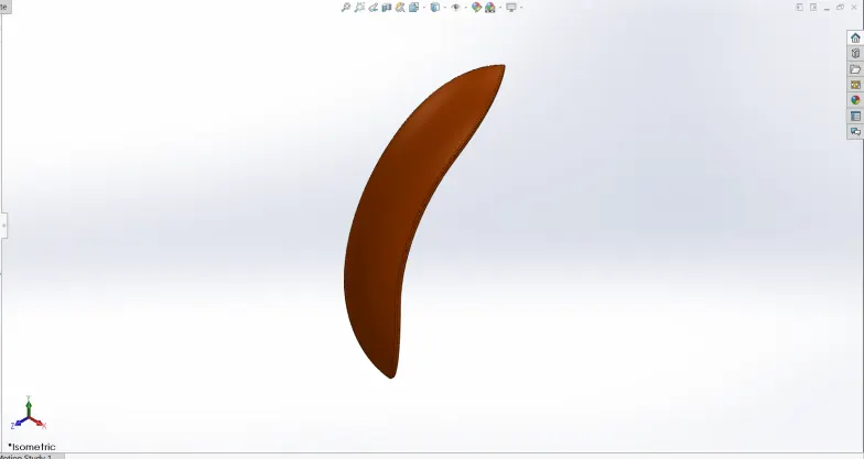
FRONT FENDER:
- Front Fender is nothing but a case of the Front wheel we will make the case by creating a sketch on the front plane and revolving it to the given angle of solid by using the revolve tool.
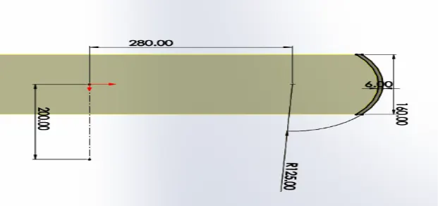
- After that by using the sketch on the Top and Front planes to the profile to get the desired profile as shown in the above sketch figures.
- After getting the desired profile we will make use of the split option and remove unwanted portions preceding the Boundary of the profile.
REAR FENDER:
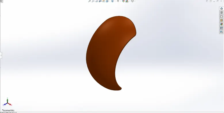
- Rear Fender is nothing but a case on the Rear wheel we will make the case by creating a sketch on the front plane and revolving it to the required angle of solid by using the revolve tool.
- After sketching on top plane having a curved surface and making split tool to remove the Unwanted surfaces and after we will use shell feature to make shell on the lower surface.
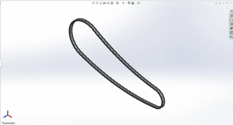
CHAIN:
- In this creation of Chain model we create the method of using Blocks . We create the profile of chain by using Sketch On Front plane After the profile is created we will create a block at a space by drawing two sketches.
- After creating two links of chain we will use them import and make their intersect to the Curve And extrude one link At a time, By using Offset extrude to extrude in a chain fashion.
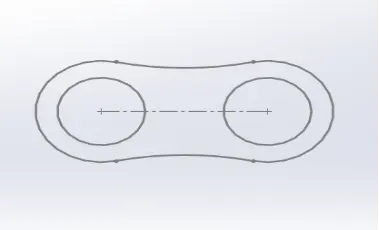
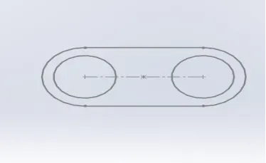
- After this extrude we will select Curvilinear Pattern to make a pattern along the curve copies of the link of the chain at the end of the curve we have again import the links to intersect the curve due to a higher radius at the corners it will pattern wrongly.
- By using these Blocks we do not have to draw the sketch again and again and can use the sketch for other parts also. After completing the parts we will group them in Solid bodies folder.
OIL TANK:
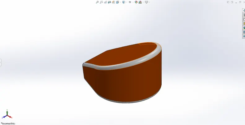
- In this Oil tank we can make this part in lot of different ways but in this part creation we have used a tool called Combine. Which makes it lot easier then the other ways.
- First we have to create a sketch on Top plane and extrude in to a solid, After we create a new sketch by taking the reference of the solid created by the Bose extrude and extrude in to solid up to next By this it become parallel with surface of the first solid . In creating second Bose extrude we have to take in mind that we doesn’t have to merge the two solids.
- By using this two solids we will use the Combine tool by selecting common which would create a solid by creating the common solid area by intersection. In this way after we give the appearances to the created solid as Siena.
PEDAL:
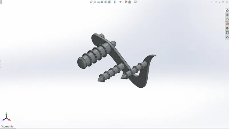
- In this profile we will create sketch in Front plane by using the following entities :
- Line
- Circles
- Splines
- Arcs
- chamfers
- After the required Sketch has been created we will use Extrude boss base to extrude to a thickness and will use this sketch multiple times to extrude the circles by using selected contours in the Extrude by Merging the results
- After extruding we will make an other sketch by intersecting the mid point of the circles by and create a Revolve base and we will extrude the remaining circles to make extrude solids.
- After this we will create a linear pattern of circles on the Revolved Boss and will create linear instances by using offset. After this we will use to create a linear pattern on other by using offset geometry extrude and we draft the edges to required dimensions and use fillets where necessary and the part obtained is shown in the figure:
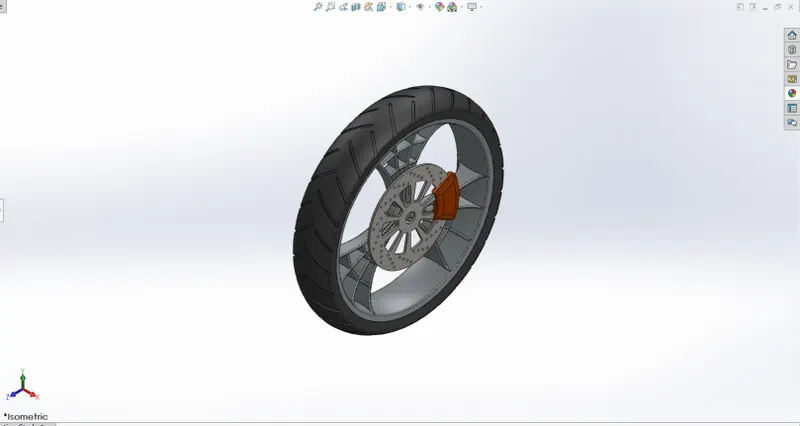
FRONT WHEEL:
- In this front wheel we will first create a sketch for the revolve and create a rim revolve to and after that create a sketch on the Front plane to create a spoke and detailing to create the spoke .
- In the detailing of spokes and create and extrude cut to remove the excess material and after creating the spokes . We will make an extrude cut on the right plane by using spline and convert entries by the selection intersection curves.
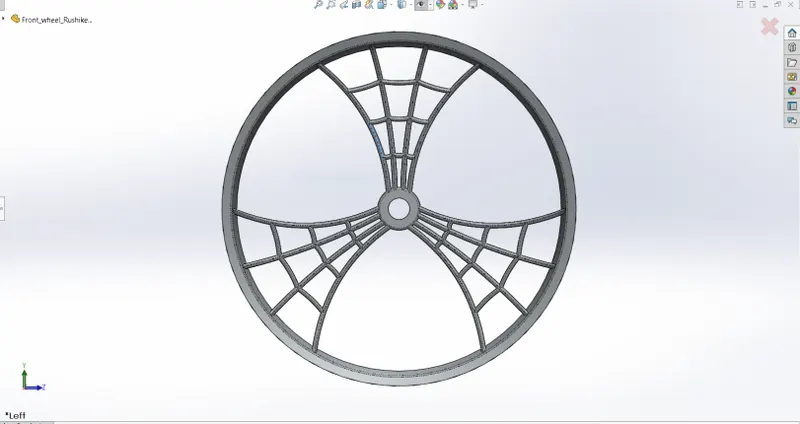
- We will make a revolve cut by selecting the inside circle and then after create an circular pattern of the spokes and make extra revolve Bose base to create a tire over the spoke.
- After this will create the side surface of inner circle of rim and make a sketch of the circle and extrude at a offset distance and make a sketch on the surface of the to make circulate pattern of the extrude cut to create detailing.
- After that create a caliper to and draft on the both surfaces .In this way we will make a Part Front Wheel.
REAR WHEEL:
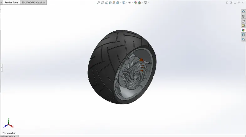
- In this Rear wheel part as we had done in the front wheel we will make a sketch on the front plane and revolve to make the rim after this we will-sketch on the Right plane to make an solid extrude by not merging it with the rim.
- After we have created a solid extrude we will make an spokes and mirror it on the remaining side of the spoke Make an extrude cut By selecting the contours option to remove the required material.
- After this to make realistic we will make an sketch again on the front plane to make an revolve inside the rim. In this way to fix the one side of the we will make a profile and revolve in the inside of the circle as shown in the below
- After this we will create an gear profile with an offset from the origin and we will also make an caliper profile as shown in the figures.
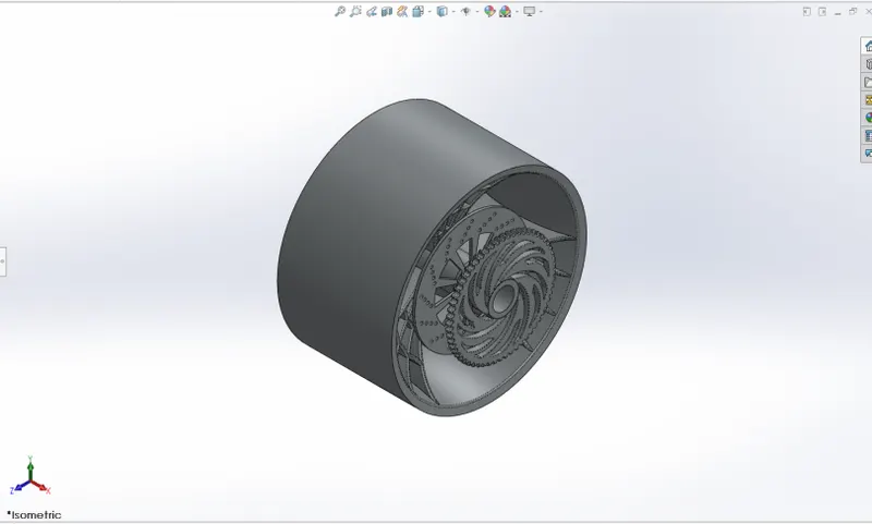
- After making these details we will male an profile for the revolve of tire by converting the entities and by selecting the required portion and ensuring the required fillets and combining the bodies and giving Appearance fitting to the profile.
FRONT FORK:
- In this we will create Front Fork which will give connection to the chassis and the rear wheel.
- In this we will create a solid profile and of one side and mirror it according the plane. We will draw Sketch on the front plane and create a revolve boss base profile . after that we will take on side of the and sketch on the surface and make extrude boss base at an offset as how in the figures and make on linear pattern at a offset distance.
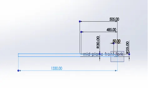
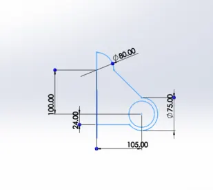
- Create a curved handle as we can see that we can say that the curve is drawings in two planes we will use the projection curve to have curve and make an plane to create a sweep along the curve path.
- we will define and also create a plane at the point and create the handle and we will make an another projection curve to create a sweep which could make the wire for brake handle.
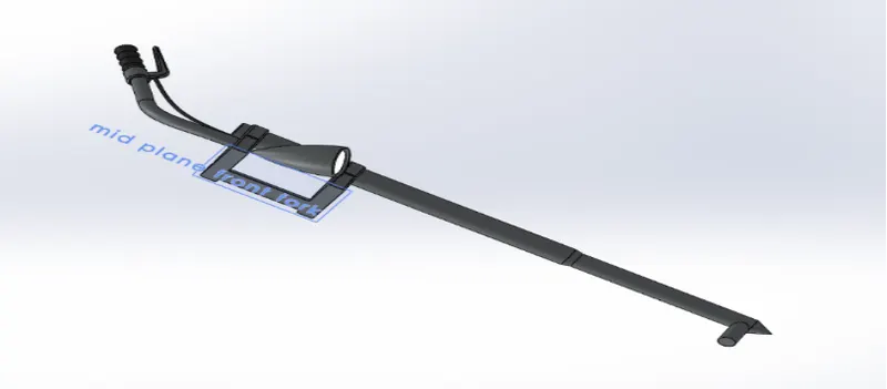
- In this way After completing the half portion we will make an mirror of the fork by selecting the surface and will mirror it along the surface which makes a another profile and use combine to combined mirrored profile with the created profile using sweep.
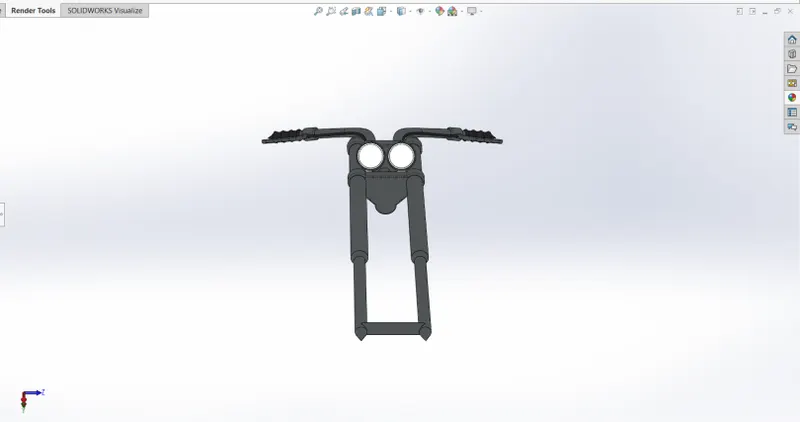
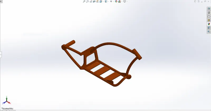
CHASSIS:
- In this Chassis part we will use a Sketch of circle on front plane and we will make projected curve by defying in right and top planes and projection and we will sweep the circular profile along the curve and mirror the solid sweep along the front plane and merge it.
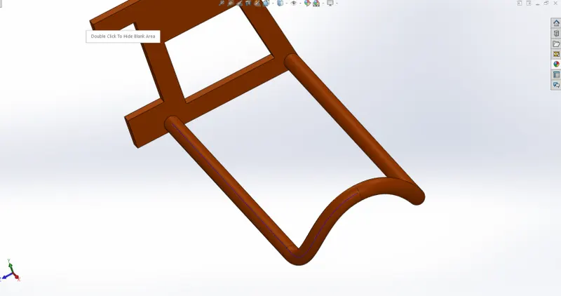
- After this we will take the end of the sweep and create a frame along the surface as shown in the above sketch and extrude it .after that we will create a plane by using the vertex option and creating circle concentric and making sweep along the curves drawn along the from plane.
- After that we have took the referenced circle and had created a another circular profile to sweep along the curve drawn in the front plane as required applications.
- At the end we have created a revolves by using the reference to the origin create a revolved solid.
- At last the required fillets are added and the appearance is set to the Metallic pain Siena.
ENGINE :
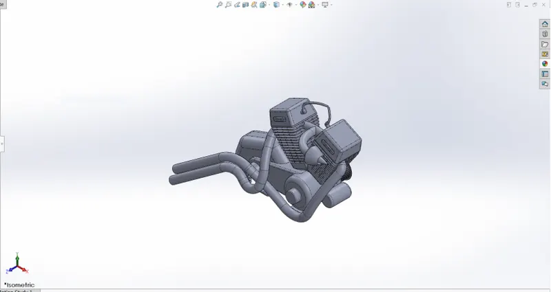
- In this Engine profile is one of the most important part of American chopper so we use the a picture of the American chopper assembly and first we have sketch a extrude boss on Front plane. After that we ha extruded it by considering both sides option.
- After these we have created two extra housing coming from the extruded surface and after this we have created an reference sketch which will make a center point for the building of cylinder by creatin a plane at the end of the line we will build rectangle by using draft outward extrude Bose base and also another by using mirror by referring to center plane created.
- After this we will sketch on the back surface of the first extrude to make housing for the transmission belt and select groves by using the circular pattern method.
- After constructing we will use the projection curves to make a sweep Bose for the exhaust pipes coming out of the cylinders. In this the inlet pipes are also created by using inlet pipes also.
- In this creation we have used the composite curves option to create a curve which is combination two projected curves. We will make stand profile on the base of the Engine profile which makes it chassis
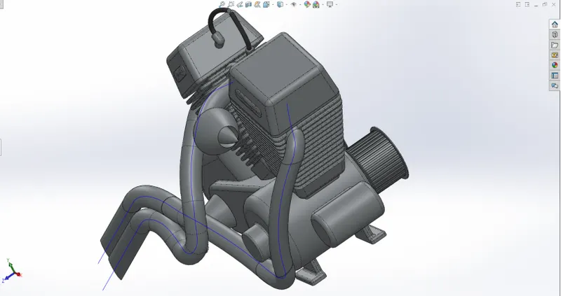
- Bythis we will get the desired Engine Profile for our American chopper.
GAS TANK:
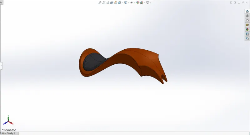
- In the creation ofGas tank we will use the surface modelling to create the outer surface after that we will convert it in to the solid.
- First we have created sketch on front plane and made an extrude by using the tool by the reference of another sketch. After this we have created a sketch for trimming the surface on from the top plane.
- After this we have created a curve by the plane created at the edge and made lofted surface to make enclosing on the surface.
- After this we have taken the another half part to create a top and front plane sketches to determine a projection curve and we created a sketches on the front plane joining the surface and curve generated by two line and by using the boundary surface tool by selecting the boundaries it had created an surface.
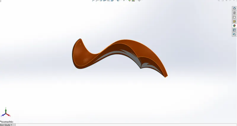
- After this we have mirrored surfaces and created slot by sketching on the Right plane and creating its curve and using swept curve option and again and knit the all surfaces and use the shell option to create to hollow space.
ASSEMBLY OF AMERICAN CHOPPER:
- Assembly of American Chopper is nothing but the collection of all the parts in single file such that we can make the m arrange and make the final product.
- First of all we will open an assembly file, and after that we will open the all the parts required for the assembly and keep opened in the background.
- We will select the tool insert components and select the files and say OK.First open the chassis after that select the right click then it will align along with the axis of the assembly.
- Then we can again insert components like Engine we does not have select but to drag near to the chassis and release then we can use the Mate tool to give mates by selecting the lower surface of the Engine to the chassis mid Rim and make an offset Distance and make it coincident .When ever a part is mated perfectly it will move along with the chassis.
- The insert an other Component like pedal and make the circles concentric with circles in the Chassis .After the part is fully mated we will make a mirror of the pedal to other side and it makes a another part and save the files.
- In this way we will go make different mates by keeping the Chassis as fixed component and we have to make in mind that we have to reference or make the planes of the parts to be aligned or mated with the planes of the Chassis part such that it will be fully constrained.
Mates used:
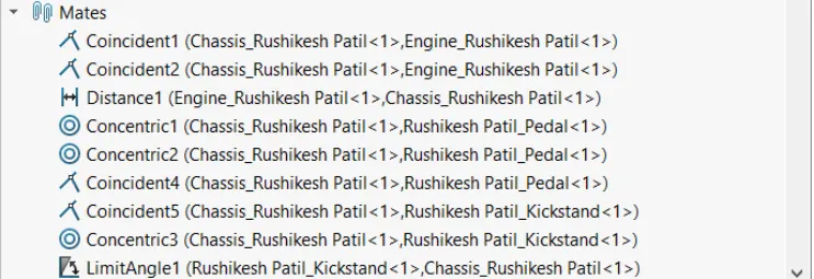
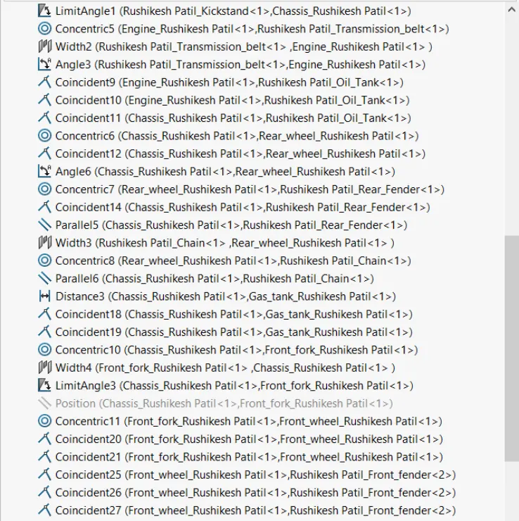
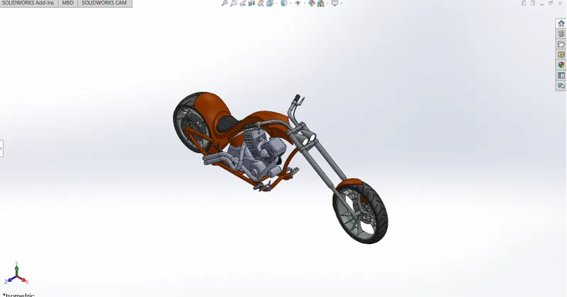
- After the assembly of the all parts we will see our model of American chopper has been created and the different views are seen in the below figures.
Isometric view:
Front view:
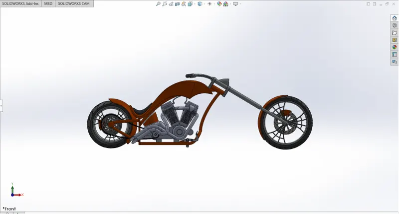
Side view:
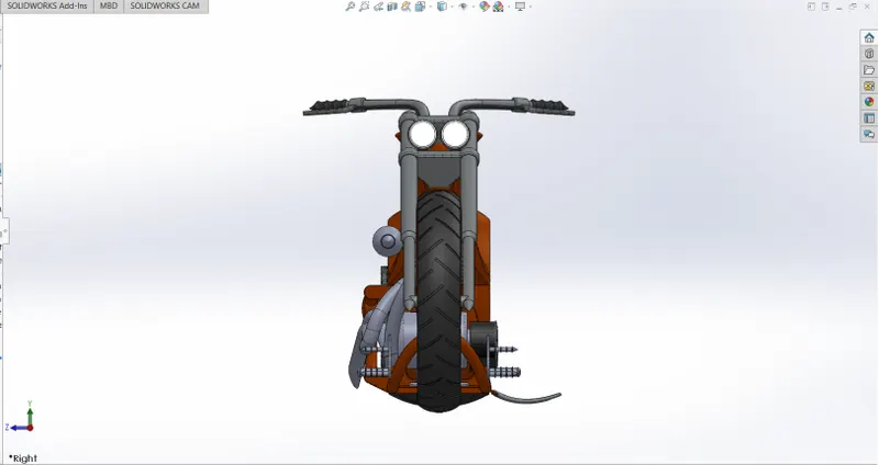
Top view:
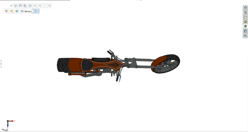
Camera view:
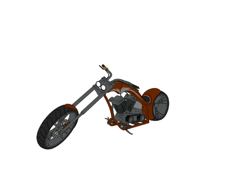
RENDERING THE ASSEMBLY OF THE AMERICAN CHOPPER:
- Rendering is nothing but adding some realistic features to make our Assembly realistic and also adding some of the features to make the parts to make real out door picture.
- We use Photoview360 to render image but first we have to make sure that these tools are on by adding the Solidworks add ins.
- To look realistic first we have to see some of the figure in view tab like lights and adding camera to view like our real time bike.
- First we make use Decals, these are the designed graphics where we can place our parts to look more realistic we use our decals on the Gas tank,Oil tank and Rear fender .
- After this we will use the lights look more realistic by using spot lights to make it more illuminated by adding different lights. We also use the environments to make it more illuminated by inserting background scenes and also to view from a specific angle we will create a camera and will make the more realistic.
- After all these Enhancements we will go to the render tools and go to render options and change the resolution of the rendered image and some of the other properties to make it look real and use the preview window to ensure that is perfect.
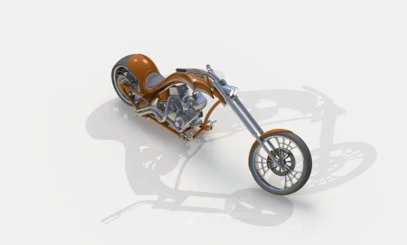
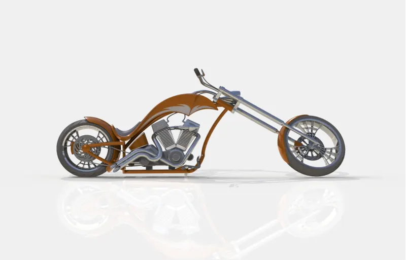
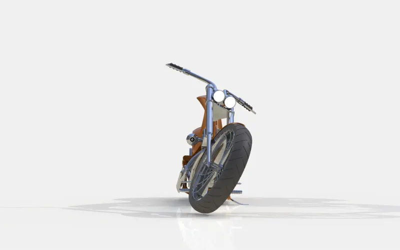
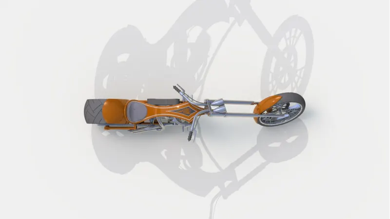
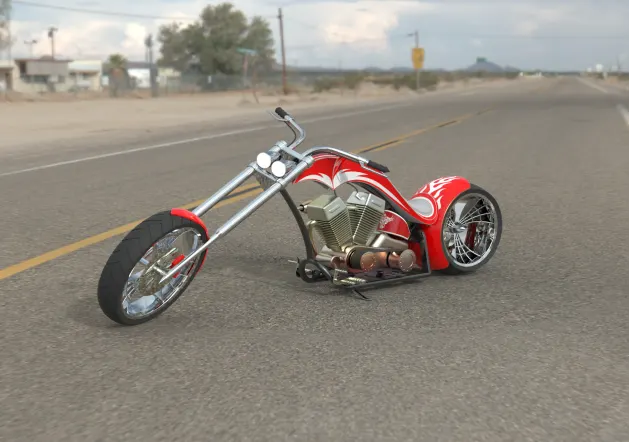
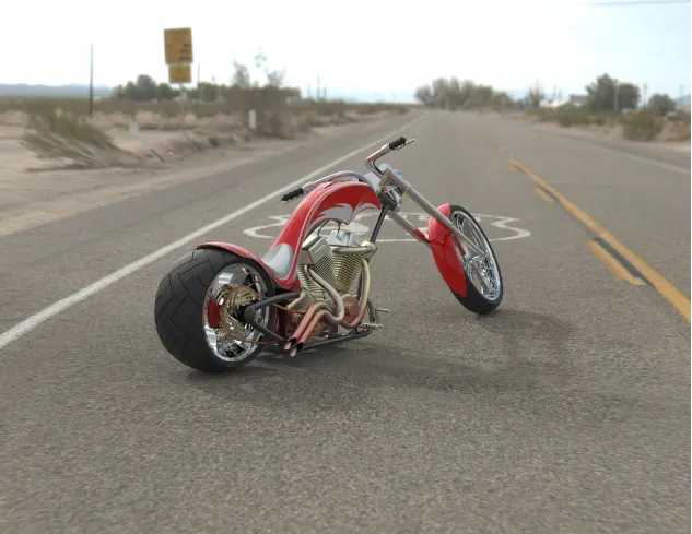
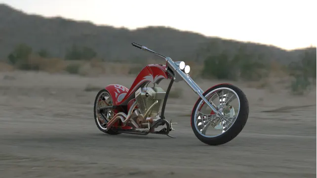
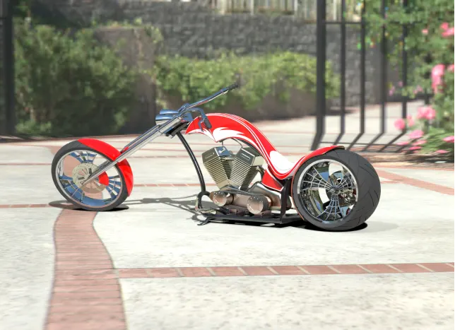
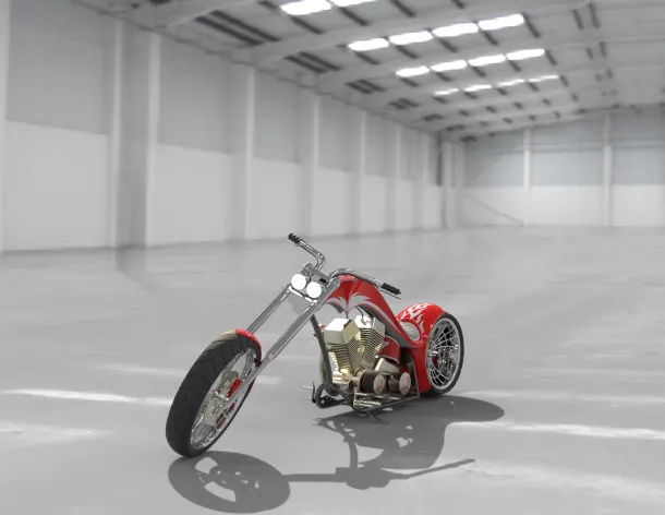
- Now make the Assembly to final render and make the Image processing properties and make it look more realistic. These are the some Views of the Final Assembly after adding decals and environments.
Isometric view:
Front view:
Side view:
Top view:
Camera view:
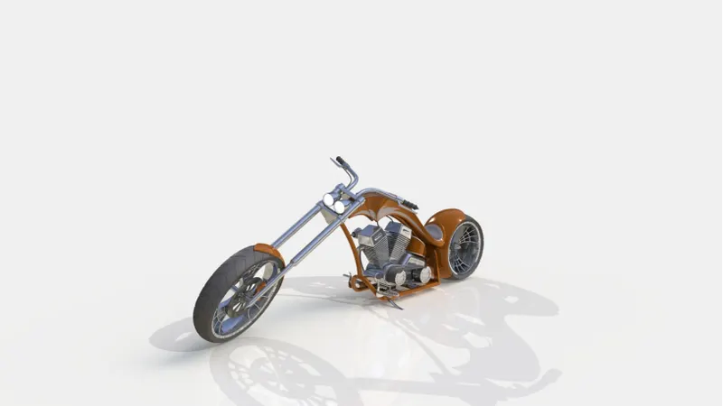
Some rendered photos of American chopper in SOLIDWORKS Visualize:
CONCLUSION:
In this we have created parts through Part Modeling through doing these, we have acquired the details of the different tools and their drawing procedures and we have also know different Mating Techniques to create an Assembly and we have learned to some rendering techniques such that when we created a render image by Photoview360 we have a made realistic image.