Week 9 - Attachment Feature Creation - Challenge 1
CREATION OF RIBS FOR THE CENTER CONSOLE COIN HOLDER FOLLOWING DESIGN RULES AND DRAFT ANALYSIS OF THE ENTIRE BODY IN CATIA
CREATION OF TOOLING AXIS:
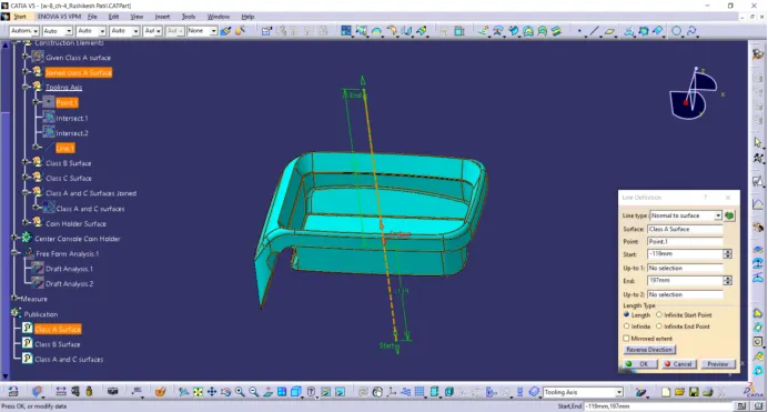
From visual inspection we can see that the tooling axis will be along the plane normal to the base of coin holder as we can see visually that hollow part of coin holder should fit either in the core or cavity.
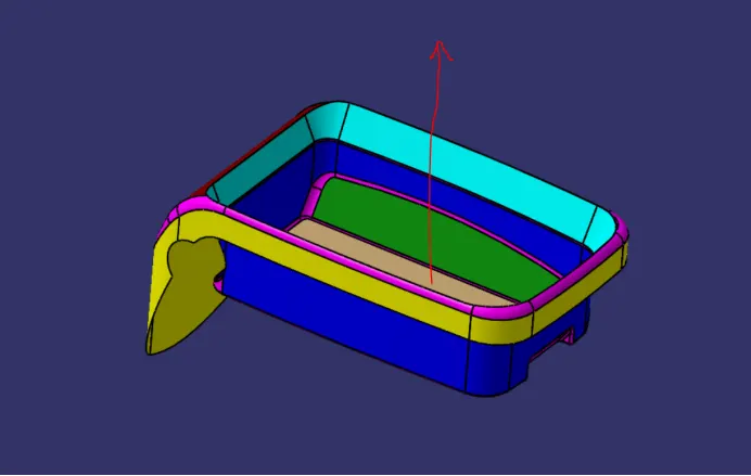
Though we have to use a side core for the hole it is recommended to use the axis normal to base surface.
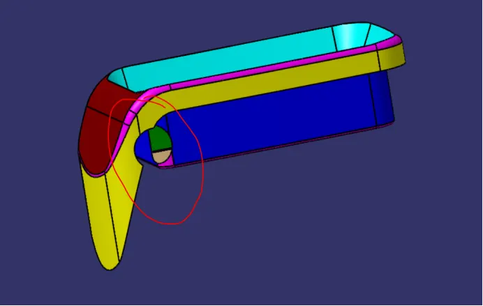
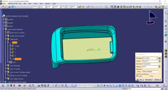
Create a center point on the base as shown below.
Create an axis system at the point imaging to the original axis.
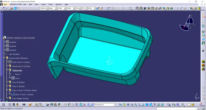
Create an Intersection line of Class A surface and ZY plane of created axis system.
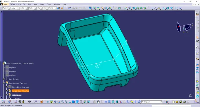
We can observe that the intersection wall lines are perpendicular to the base surface.
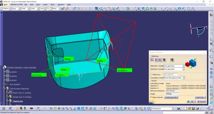
We can observe the same problem along the intersection along XZ plane as the walls are exactly perpendicular to the base surface.
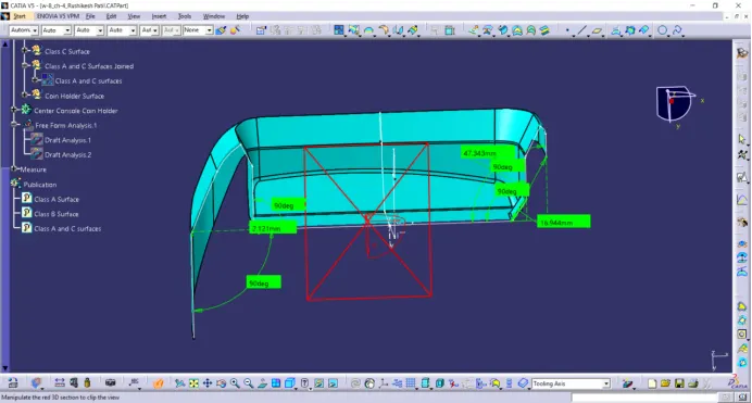
Since the class A surface should be created with a minimum draft along all ghe surfaces because the plastic body created from class A should be ejected easily from core and cavity and surfaces with draft are easy for ejection after cooling the part.
Since the class A surface is not provided with sufficient drafts and modifications to the class A surface are prohibited for us so we proceed further taking the axis normal to the base surface as tooling axis and create a plastic component of thickness2.5mm.
Draft Analysis of Class A Surface:
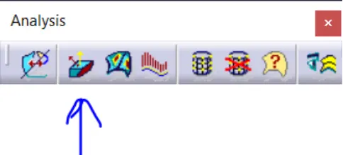
Click on the feature draft analysis in Analysis tab
Or Go to insert >Analysis > Feature Draft Analysis
Click on the compass in direction row and align the compass along the tooling axis as shown below. Also disable the analysis under running point option in display row in draft analysis tab.
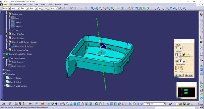
Some times the compass disappears or will be placed far fron the surface, zoom out from the surface and disable and enable the compass to see the compass and drag it to the tooling axis.
Once the compass is aligned lock the compass.
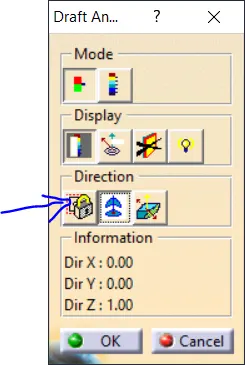
After locking left click anywhere on the surface. It will look as shown below.
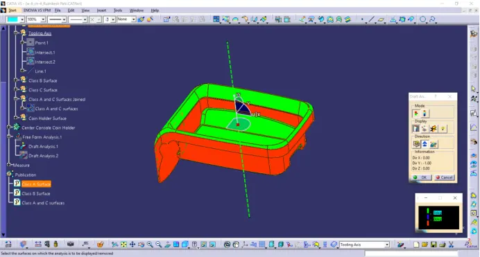
The green colour on the surface shows that the entire surface is provided with a minimum draft of 3 degrees.
The red coloured surfaces have a negative draft angle but we proceed further for plastic part creation.
Creation of ribs:
Extract the surface on which the ribs are to be created and draw a line of beadth of rib as shown below.
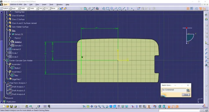
Extrude the line along the tooling axis to a height of 12.5 mm following the design rules as the height should be <= 5*thickness of part.
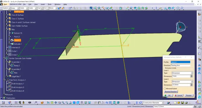
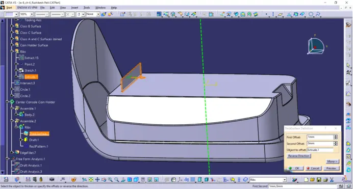
Thicken the surface to a thickness of 1 mm following the design rules as it be equal to 0.4*thickness of part.
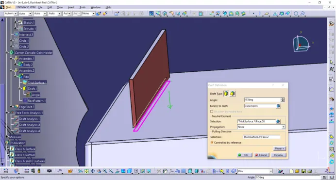
Create a draft of 0.5 degrees to the four faces of rib following the design rules.
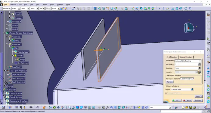
Create another rib using pattern with the spacing of 6mm following the design rules as the ratio of height of the rib to the distance between the ribs should be in the ratio 3:1 (for steel) and 2:1 is also preferred.
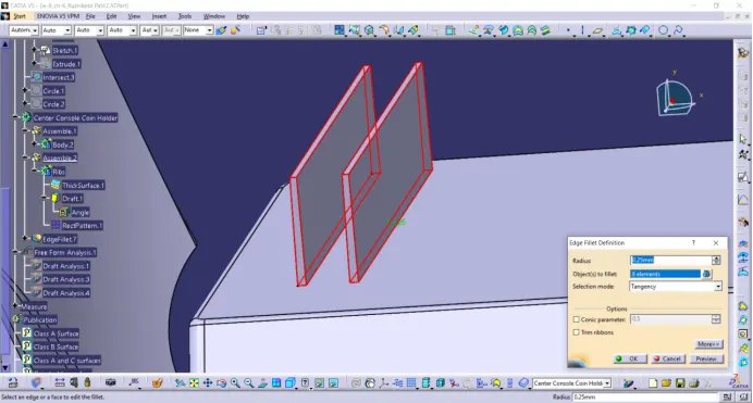
Create fillets to the ribs with radius of 0.25mm following the design rules.
For checking the rib root thickness create an intersect between XY plane and the entire part. Crate tri-tangental circles at the bottom of the ribs and check for the diameter it should be in the range of + or - 30% of thickness of the part.
The below figure shows the measurements which followed the design rules.
Draft analysis of the entire part.
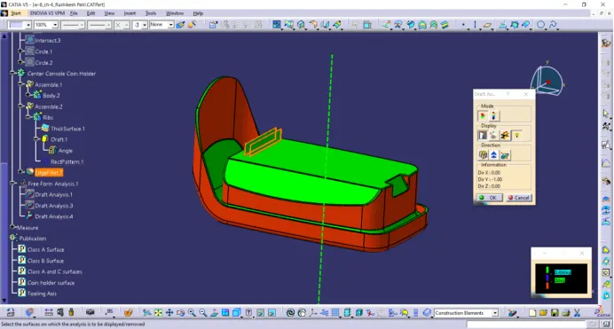
Since the draft given to the ribs is 0.5 degrees the upper limit of the range is changed to 0.49 degrees.
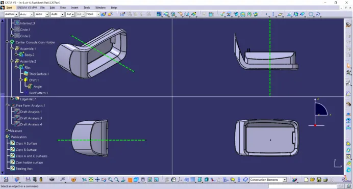
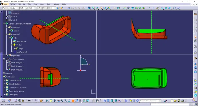
Various orientations of the Part;
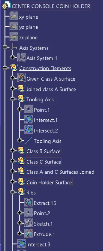
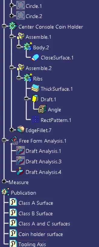
Tree Structure: