Week 7 State of charge estimation
1. Three test cases from harness dashboard of design and test lithium-ion BMS algorithms model.
We have to change the test cases option from the block name Test Sequence Variant shown in the image. It has 3 selections named 1,2, and 3. 1 means Balancing, 2 means charging and 3 means driving.
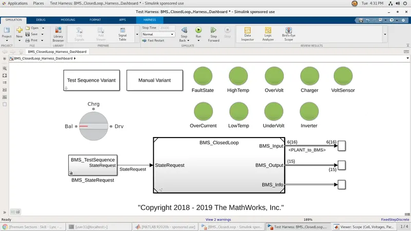
a) Balancing
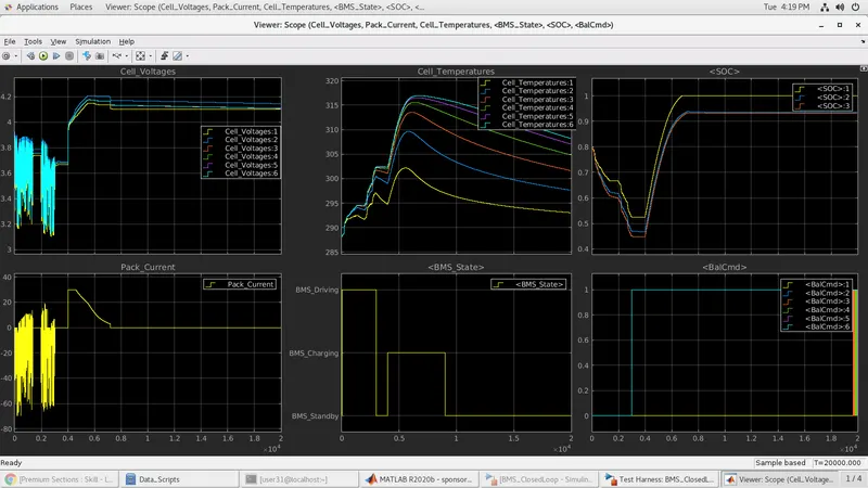
From the above plots, we can clearly see that the first 3000-sec state is in driving mode means discharge will happen that's why we see huge disturbances in pack current and cell voltages plot. Pack current is negative because it shows discharging cycle and at the same time cell voltages and SOC also reduces and cell temperature increases. But exactly at 3000sec, we see standby mode getting activated. At this moment, parameters for pack start normalizing, pack current becomes 0 as no charging or discharging is happening for the module. So cell voltage also shows a constant value and cell temperature starts reducing. But again at 4000-sec charging cycle starts and cell voltages increases, pack current shows the current value at which charging is happening. And because we see a steep delivery of current at 4000 sec i.e. nearly about 30 that's why we see cell temperature increases at a very high rate and cells getting charged to nominal voltage values soon enough. Here in this model, we are only using a controlled current (CC) charger circuit, whereas it should be a combination of controlled current and controlled voltage circuit (CC+CV). This may be a reason why we see so much hike in temperature values. But just after 5000 sec we see pack current plot decreasing to 0 values in next 2000 sec parameters like temperature and cell voltages starts normalizing. Soc for cell 1 becomes 100% as it was well thermal insulated that's why it shows lower temperature values at every cycle when compared to other cells. But because other cells were not well thermal insulated we see lower SOC values and temperature remains higher for these cells when compared to cell 1.
b) Charging
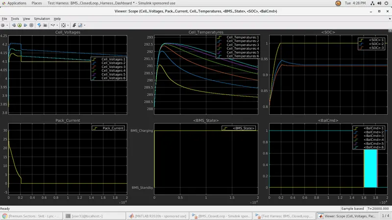
Here in test case 2 i.e. charging cycle only where balancing will also be active at the same time, we see cells being charged with a controlled current source with nearly 30 A supply. Due to such peak charging values we see rapid increases in cell voltage limits and also cell temperature increases abruptly. Same as mentioned in test case 1 we see due to improper thermal insulation of other cells than cell1 we see SOC of other cells remains less than SOC of cell1.
c) Driving
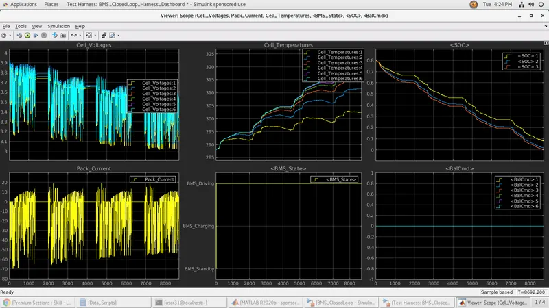
Now in test case 3 we see that it runs a model in only drive mode means the extraction of current happens that why we see pack current more on the negative side of the plot. And because discharge is happening Cell voltages will drop below 4.2v nominal voltage values. Cell temperature, in this case, doesn't show a sudden increase it increases with a lower rate. Soc drops for each cell due to extraction and all these actions are happening under no cell balancing command.
2. Coulomb Counting and its relevance
Method:
- Different applications impose different battery-pack performance management priorities. To function reliably, EVs need to have continuous updates for the estimates of two fundamental battery quantities: How much energy is available in the battery pack and how much power is available in the immediate future. An estimate of energy is most important for EV. Energy is an ability to do work and is a total quantity measured in Wh or kWh. Energy is a fundamental input to vehicle range calculations—it tells you how far you can drive.
- Ideally, we would like to be able to measure available energy and power directly and then report these values to the vehicle computer. Unfortunately, no such sensor exists. Instead, we must compute available energy and power estimates using more basic quantities as inputs to the computation.
Coulomb counting:
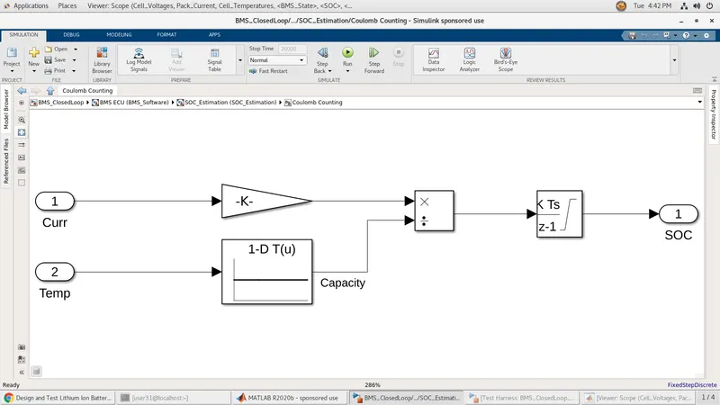
- The Coulomb counting method is one of the most general and simple methods of estimating the SOC. We use it for a baseline comparison for more advanced methods. The Coulomb counting method measures the current of the battery and integrates the current overtime to estimate SOC. Limitations of the method, which lead to other projects along these lines, include the fact that inaccurate current measurements accumulate to large errors, whereas accurate current measurement is expensive. Other factors such as temperature, battery history, initial SOC, and cycle life also influence the precision of the SOC estimate. Practically speaking, the Coulomb counting method cannot capture some phenomena, such as decreasing SOC when the battery is resting, and variations with temperature changed.
- To determine available capacity, coulomb counting relies on the integration of the current drawn from and supplied to a battery over time.
- The Coulomb counting method measures the discharging current of a battery and integrates the discharging current over time in order to estimate SOC. Coulomb counting method is done to estimate the SOC(𝑡𝑡), which is estimated from the discharging current and previously estimated SOC values, SOC(𝑡𝑡 −1).
- SOC is calculated by the following equation: SOC (𝑡𝑡) = SOC (𝑡𝑡 − 1) +𝐼𝐼 (𝑡𝑡)𝑛𝑛Δ𝑡𝑡
- Coulomb counting is advantageous in terms of a simple structure and its ease of implementation. However, some problems make it difficult to accurately estimate battery SOC by coulomb counting. Because battery capacity and efficiency are significantly influenced by operating temperature and current direction, these factors should be considered to correct for battery SOC. Sensor accuracy is also important because accumulated errors can lead to a drift in the estimated battery SOC. Furthermore, one of the main problems in coulomb counting is that it is necessary to calibrate the initial battery SOC.
- In order to improve SoC estimation, coulomb counting and voltage-based methods can be combined. In this method, a cumulative error of the counting integrator can be removed by a counter calibration based on the OCV characteristics. The calibration can only be done if the battery is not in use. Otherwise, the current is integrated to get the relative charge in and out of the battery
For the above-mentioned model, it uses 2 ways to do SOC estimations
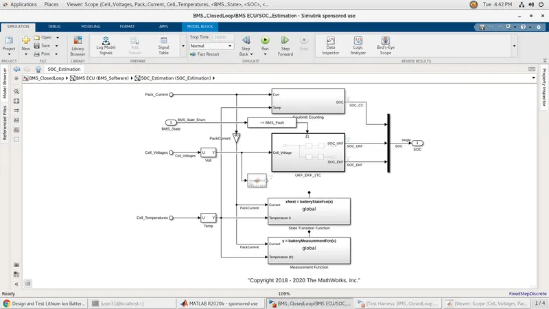
1. Coulomb Counting - It integrates current that enters and leaves cells to keep track of safe charging limits. It has a limitation of lack of voltage feedback leads to wrong initial vales.
2. Kalman Filters (Unscented & Extended) - Both are variations of nonlinear common filters and they rely on a model unit cell to predict terminal voltage resulting from a current stimulus. Estimating the internal cell state, SOC among them by comparing these predictions again voltage of terminal voltage. The choice between unscented and extended is based on system nonlinearity. The one with less can be done with extended and more with unscented.
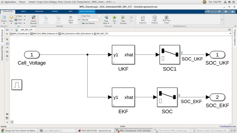
Here in this model, majorly EKF is used as nonlinearity is mild and nonlinearity is shown using OCV AND SOC relationship.