Week 12:Project-1-Meshing of Door Inner Panel Challenge
Aim: Mesh the side door of the car model for given quality criteria and assign thickness.
Quality Criteria - Target Element Length = 4 Units
| S.N | Quality Criteria | Value |
| 1 | Aspect Ratio | 5 |
| 2 | Skewness | 45 |
| 3 | Warping | 15 |
| 4 | Taper | 0.5 |
| 5 | Min. Length | 2 Units |
| 6 | Max. Length | 6 Units |
| 7 | Min angle Quad | 45 |
| 8 | Max angle Quad | 135 |
| 9 | Min angle Tria | 20 |
| 10 | Max angle Tria | 120 |
| 10 | Tria % | 10 |
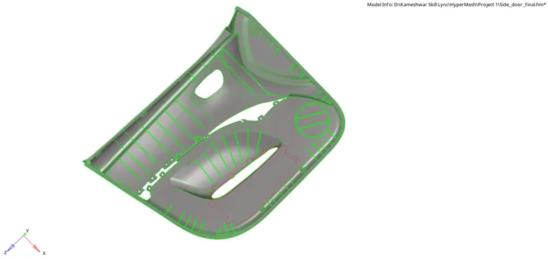
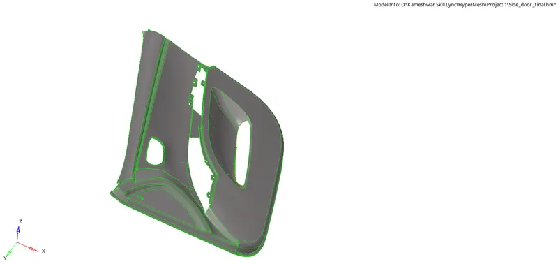
Procedure: To start with meshing on any component we have to go through several preliminary stages, which include geometry cleanup, mid surface extraction, mid surface clean up, and set up as per mesh parameters.
So, in hypermesh we need to first check for solids in the geometry, after import the model. Now to delete these solids we will use the universal delete option and change the selection type to solids and select and delete. But in our case, we don't have any solids present in the model.
Now we need to check for any geometrical errors manually by zooming in different areas, rotating, and checking at different locations.
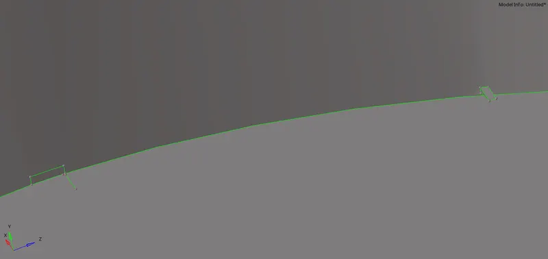
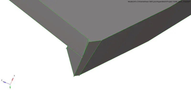
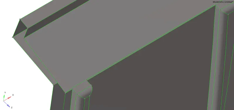
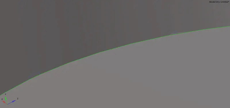
Correction of error.
Now we can extract mid-surface. For this, we will be using the mid-surface option under the geometry main menu bar. Under this option, we will have multiple options to extract mid-surface in extraction options, if one method doesn't give the best result we should always use another option before proceeding further or using manual mid-surface extraction. If none give results we will extract mid-surface by manual mid-surface extraction method i.e. offset surfaces. Here, in our case, we got results from the offset+planes option in the extractions options under mid-surface. In our case, we were not able to extract mid-surface automatically so we used the manual mid-surface extraction technique.
If you select all surfaces in one go it will create mid surfaces in one component only. So for this either we need to generate mid surface component by component or go in one go and later organize them separately by creating new components. Tools - Organise - select component by face option and move it to the new component.
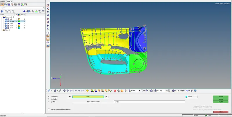
So now after organizing we can easily work further component by component. Now we will be first cleaning mid-surface geometry if needed and then set the feature lines as per mesh parameters provided. Set here means toggling unwanted feature lines, Creating new construction lines, and defeaturing if needed in some area that doesn't follow minimum element size criteria. And create washer cuts near holes if required.
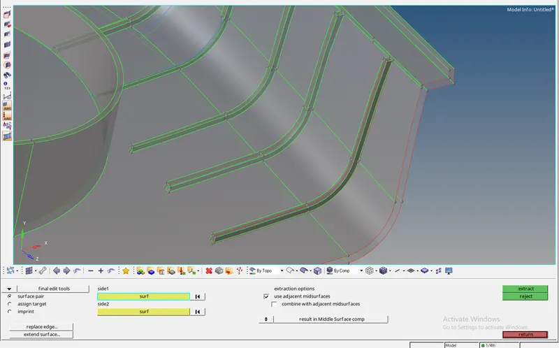
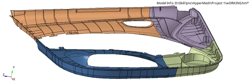
So for this model defeaturing of many feature lines is required and also new construction lines will be made by generating midline from 2 lines that define that feature and then cut surface along those lines. I will highlight the area that will require special attention for setting geometry as well while generating mesh.
Here we toggled most feature lines and also created midlines and trimmed surfaces using these midlines. This can be done by using Geometry - lines - mid-line. And then to trim the surface we use Geometry - Surface edit - trim with lines. And because most of the surfaces were symmetrical in nature we delete symmetrical surfaces using the universal delete option.
This way we set the geometry as per mesh parameters provided for this component, this is a manual method we even have an auto cleanup option to set the geometry as per mesh criteria. But that needs a good understanding of how to set parametric file settings.
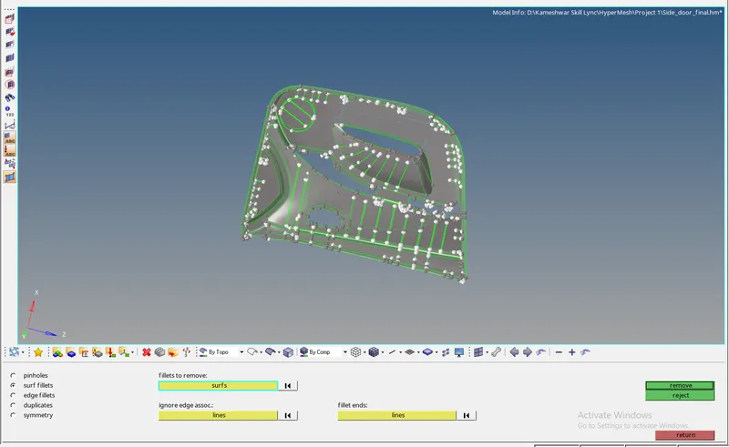
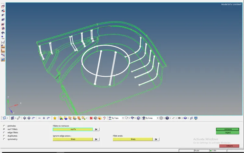
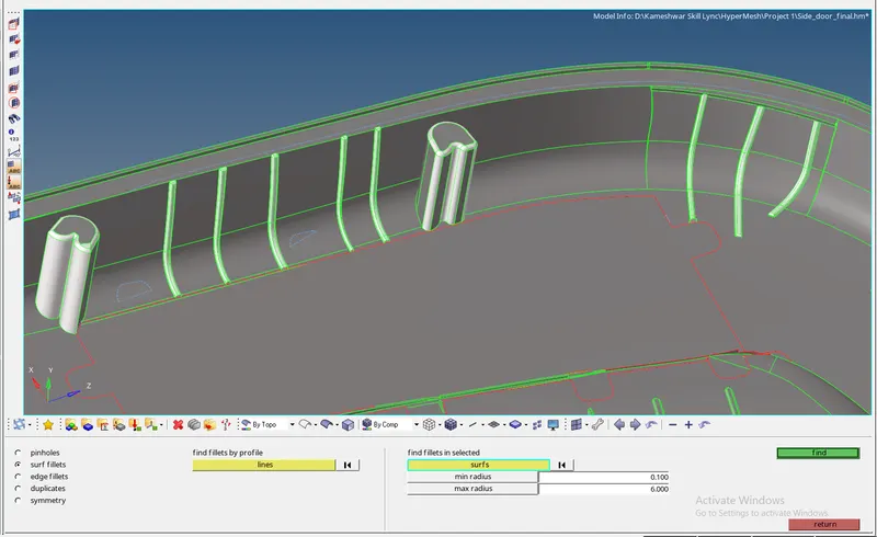
Now we can start with meshing area by area always start with feature capturing first and from there proceed further this way we started meshing by using option 2D - auto mesh - select surface to mesh - define mesh parameters asked - and mesh.
Tips to have good mesh:
- Keep number on nodes same on opposite edges of an area.
- Prefer quad elements over tria.
- No trial should be there on free edges.
- No opposite tria should be there in model
- Rotating quad should not be there we can have tria in place of rotating quads if that area demands it.
- Mesh flow should be checked, which means meshing should not be in a zigzag way. It should be following straight-line paths. In curve regions, we can have flowed along the curve.
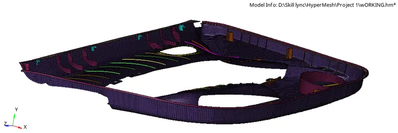
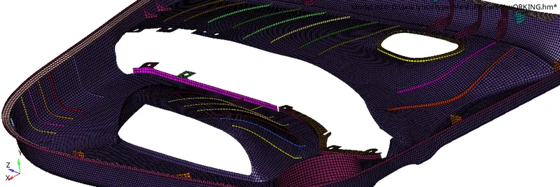
This is the best, that personally, I can capture this special feature that we discussed, still, some more work can be done on these features. It has to be noticed the mesh type depends on the type of solving to be done like here we meshed for crash analysis specifically where mesh type will affect the results more, as we account for nodal displacement here for stress-strain calculations. So above mentioned tips for good mesh are for crash applications it may differ from solving to solving. Also as we know tria is stiffer than quads and nowadays due to pedestrian safety hoods are made less stiff so that head impact injury rate reduces, so due to this reason we capture most areas of the model by quads instead of tria and keeping trias only in the area where we can't do anything.
Now, we need to check for element quality. Element quality means mesh quality criteria provided for this model which I shared at the top. In hypermesh, we have multiple ways to check the same. We can go to Tools - check elements and pass values that are provided to us. Or we can also provide quality criteria defined in criteria file settings before starting meshing.
This way we can detect where we have elemental quality issues. Mostly for this model we had errors like warpage, Minimum length error, maximum length error, jacobian, and aspect ratio. To deal with all these issues we used options like swap edges, Combine tria, align nodes, translate, drag tria, or in very few area elements optimize. These all cleanup tools are available in the 2D-quality index - Cleanup tools, and also in geometry node edit. Smooth helps sometimes, and remesh most of the time helps a lot.
Some area warpage can't be ignored so we left it as it is, but rest we cleared all.
Because we have divided the model into four parts we will see that element connectivity will not be there, so now we need to first check for free edges to detect where connectivity is not there, and then if there are any we delete free edges first and then again select elements and do equivalence by giving tolerance value. Most of the nodes which will be within tolerance limits will connect automatically
This way we did the equivalence for our components. Now we will check for normals direction, all faces should have the same normal's direction other we need to correct the normal's direction to keep it all same.
This way we checked the normals for all components and we find normals to be in their correct positions.
Then we need to assign thickness to the mid surface so for this we will create a new property card and component card for each different thickness value and using organize option we will assign the right mid surface with the right thickness card.
Now our work for this model is done. We can rap up now for this model.
Conclusion:
In this challenge, we learned about automatic and manual mid-surface extraction. Also, geometry clean-up checks and rectification if required. Then how to capture features present in the model as per provided mesh criteria. Rectification of elements manually, if they are failing for quality criteria and this is done after learning about the type of failure and its rectification techniques. Also, a deep study to understand failure is done to understand what is the meaning of that failure. And at last element connectivity importance is seen as if connectivity is improper then during solving, we will wrong results and even improper transfer of loads will happen from element to element. The orientation of all elements should be the same as it also contributes to better solving and its results. And before basic component study should be done and type of analysis to be done should be known as it will help to generate the best suitable mesh for the component.