Meshing Instrument Panel Substrate in ANSA
Aim: Meshing the provided model of Instrument Panel Substrate.
Procedure:
Before doing any operation on provided model it is always better to know little about it.
So, instrument panels are often made of acrylonitrile-butadiene-styrene (ABS), ABS/polycarbonate alloys, polycarbonates, polypropylene, modified polyphenylene ether (PPE) and SMA (styrene-maleic anhydride) resins. These plastics allow for complex designs in items such as airbag housings, center stacks for instrument panels, and large, integrated instrument panel pieces.
Wholly integrated single-piece units can be manufactured from all-urethane and all-polypropylene resins. This results in a seamless instrument panel with greatly reduced NVH levels, molded-in color and with significant cost savings for the manufacturer. Cost effective post-consumer and in-plant recycling are also achievable.
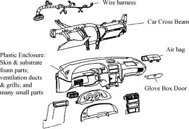
So, to start with modelling this component we need to follow few steps:
1) Perform topo operation to stich all faces and do orient to give single orientation.
2) Do geometry clean up if any like triple cone, needle faces, Cracks etc.
3) Check for measurements at multiple places of component and compare it with the provided quality ranges and if the area doesn't follows it than do necessary changes to model like defeaturing, new faces construction after deleting existing, Toggling off construction lines which are not needed. Divide faces to multiple regions to have better mesh flow.
5) After this as per the measurements value we got we will check we need to do shell meshing or solid meshing. Here in our case we found thickness of all regions less than 6 mm so we performed shell meshing on whole component after mid surafce extraction. And after mid surface extraction assing property to that mid surface is necessary.
6) After mid surface extraction for whole component we will start with meshing this component using mixed type mesh in which both tria and quad elements are there.
7) Mesh was performed by taking care of several points like no tria on edges, no adjacent tria, No opposite trias, Total tria concentraion to be less than 15%. Even number of nodes in hole and punched regions.
8) Taking care of all these points we did meshing and in some regions majourly where triple cones were there, there we faced quality issues which can't be resolved also.
Learning Outcomes:
* Dealing with such a huge geometry by breaking it into several small portions.
* Better understanding on shell mixed type meshing as it was having more complex regions to take care.
* Quad is preffred over trias and trias is preffered over rotating quads.
* How to eliminate trias.
Conclusion:
Better mesh flow can be achieved by cutting faces into multiple portions. Approximations for some regions becomes necessary like capturing cylindrical shapes in solid using cross or we can also do it by offsetting outer surface to middle in both cases we will have either addition of volume or subtraction of volume.
Drive Link:
https://drive.google.com/file/d/1UcoeeMhLpFxt8tZyYrzprv2PeLcpnXrY/view?usp=sharing
Refrences:
https://www.automotiveplastics.com/automotive-plastics-today/interior/