Meshing and providing Connections to Suspension Assembly in ANSA
Aim: Meshing and providing connections to Suspension Assembly.
Procedure: Firstly, we need to arrange a CAD model with good quality for doing all these tasks. It is provided to us already and it should be in provided formats only (i.e. step, iges, stl) so that it is workable in ANSA workbench.
Now before starting work on our model it is always better to understand its importance in industry and facts behind it. So, coming up with this question several questions arises in mind like:
Vehicle Suspension System:
A system of mechanical linkages, springs, dampers that is used to connect the wheels to the chassis is known as a suspension system. It has usually done two works-controlling the vehicle’s handling and braking for safety and keeping the passengers comfortable from bumps, vibrations, etc.
Simply stated, its a part of an automobile that negates most of the forces that the car gets from driving on the road making sure the cabin stays still.
A suspension works on the principle of force dissipation which involves converting force into heat thus removing the impact that force would have made. It uses springs, dampers and struts to achieve this. A spring will hold the energy while a damper will convert it into heat.
Functions of a suspension system:
The work of a suspension is to provide comfort to the cabin, make sure the car stays in contact with the ground and that the driver has control over the tires at all points which is just achieved by having contact with the road.
It also helps to maintain correct vehicle height and wheel alignment.it also control the direction of the vehicle and has to keep the wheel in a perpendicular direction for their maximum grip. The suspension also protects the vehicle itself and luggage from damage and wear.
Controlling of vehicle is referred as wheel allignment. There are certain terms linked to it like caster , camber, and toe-in/toe-out.
Caster : Angle made by the steering axis with the vertical axis when looking at a car from sideways.
Camber : The angle made by the tire and the vertical axis of the car is called camber.
Toe-in/Toe-out: If the front tires are further apart from the rear tires its called a toe out. Having the front wheels more inwards compared to the rear wheels makes it toe-in.
Types of suspension system:
1) INDEPENDENT SUSPENSION SYSTEM
This system means that the suspension is set-up in such a way that allows the wheel on the left and right side of the vehicle to move vertically independent up and down while driving on the uneven surface. A force acting on the single wheel does not affect the other as there is no mechanical linkage present between the two hubs of the same vehicle. In most of the vehicle, it is employed in front wheels.
This type of suspension usually offers better ride quality and handling due to less unsprung weight. The main advantage of independent suspension is that they require less space, they provide easier steerability, low weight, etc.. Examples of Independent suspension are
i. Double Wishbones
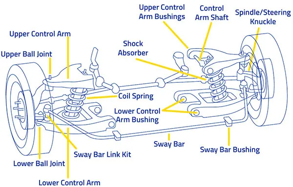
It is an independent suspension system design using two wishbone-shaped arms(called A-ARM in USA and WISHBONE in the UNITED KINGDOM)to locate the wheel. Each wishbone or arm has two mounting points to the chassis and one joint at the knuckle. The angle movements of the compressing and rebounding wheels can be managed by using arms of unequal length.
The main advantage of the double wishbone suspensions is that they allow easy adjustments of camber, toe and other properties. This type of suspension also provides increasing negative camber gain all the way to full jounce travel. On the other hand, it takes more space and is slightly more complex than the other system like Macpherson strut. It also offers less design choice.
ii. MacPherson Strut
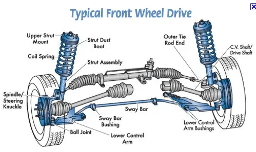
This type of independent suspension got its name from Earle S. McPherson who developed this design. The MacPherson strut is a further development of the double wishbone suspension. The main advantage of the MacPherson is that all the parts providing the suspension and the wheel control can be combined into the one assembly.
It makes it easy to fit in a transverse engine. This design is very popular due to its simplicity and low manufacturing cost. The disadvantage is that it is more difficult to insulate against road noise. for this, an upper strut mount is necessary, which should be decoupled as possible. It also requires greater clearance height.
2) DEPENDENT SUSPENSION SYSTEM
In Dependent Suspension there is a rigid linkage between the two wheels of the same axle. A force acting on one wheel will affect the opposite wheel. For each motion of the wheel caused by road, irregularities affect the coupled wheel as well.
It is mostly employed in heavy vehicles. It can bear shocks with a great capacity than independent suspension. Example of this system is
I. Solid Axle.
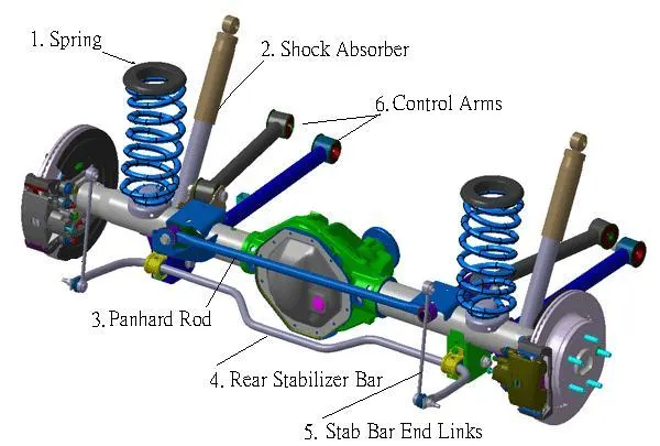
A solid axle or beam axle is a dependent type suspension. It is mostly used in rear wheels in which the rear axle is supported and located by two leaf springs. The vertical movement of one wheel influences the other. They are simple and economical to manufacture.
They are so rigid that there is no change in track width, toe-in, and camber on a full bump which helps in the low wearing of tires. The main disadvantage is that the mass of the beam is included in the unsprung weight of the vehicle which results in low ride quality. The cornering ability is also poor due to zero camber angle.
3) SEMI-INDEPENDENT SYSTEM
This type of system has both the characteristics of a dependent as well as independent suspension. In semi-independent suspension, the wheel move relative to one another as in independent suspension but the position of one wheel has some effect on the other wheel. This is done with the help of twisting suspension parts. Example of semi-independent is
i. Twist Beam
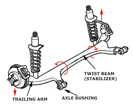
The twist beam suspension is also known as a torsion-beam axle. These are mostly based on C or H shaped members. The cross beam of the H-shape holds the two trailing arms together and provides the roll stiffness to the suspension.
It is mostly used in the rear wheel of the cars. It is very favorable due to its low cost and it is very durable. It is simple in design and is very light in weight. But on the other side camber angle is limited and the roll stiffness is also not very easy. The characteristics may be unsuitable.
Components of suspension system:
1) Spring: The job of a spring in a suspension system is to store the energy that is generated when the car goes through a bump. A spring or a coil stores energy by compressing its size thus making any type of force into energy. There are two types of springs used for suspension a coil spring and a leaf spring. A coil spring is a common one which most you might have seen. A leaf spring is used on a solid axle so basically in trucks and has very high energy storing capacity compared to a coil spring.
2) Damper: To help springs and keep your car in control dampers are necessary. The energy stored by the springs need to go somewhere else it will be released by the springs again with some minor transfer loss and your car will keep on jumping around at every crack in the road. After the spring stores the energy, the dampers or shock absorbers start working. Inside a damper is a piston with small holes in it and some pressurised oil. When the spring transfers the energy to the damper the piston moves through the pressurised oil by using the energy of the spring. Passing through the oil generates heat, successfully converting the energy of the bump in the road into heat energy and negating any energy left which would have caused the car to jump.
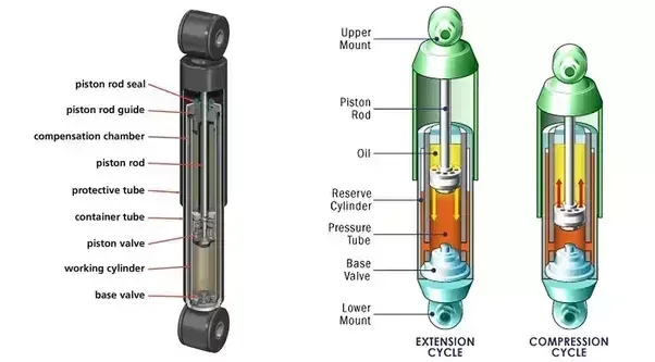
Strut is a damper wrapped in a coil spring. It is a structural component of a car.
3) Steering Knuckle/Upright: It is the component of the suspension system that is mounted over the wheel’s hub through which the wheels and the suspension of the vehicle connect with each other by the linkages provided. A knuckle is provided with the king-pin and the caster angles that help the front wheels of the vehicle to steer in right or left direction which in turn steers the vehicle. A knuckle provides housing for central bearing over which the wheel’s hub rotates along with the rotation of the wheels.
4) Ball Joint Pin and Ball Joint Knuckle: Ball joints play a critical role in the safe operation of an automobile's steering and suspension.
5) Sway Bar and Coupling Bar: An anti-sway or anti-roll bar is intended to force each side of the vehicle to lower, or rise, to similar heights, to reduce the sideways tilting (roll) of the vehicle on curves, sharp corners, or large bumps. With the bar removed, a vehicle's wheels can tilt away by much larger distances.
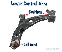
6) Control Arm: A control arm, also known as an A-arm, is a hinged suspension link between the chassis and the suspension upright or hub that carries the wheel.
------------------------------------------------------------------------------------------------------------------
Now after knowing about our model we can start doing meshing and at last provide connections to it.
So, to start with these task we need to follow few steps:
1) Perform topo operation to stich all faces and do orient to give single orientation.
2) Do geometry clean up if any like triple cone, needle faces, etc.
3) Set PID to each PID region present in it or in other words to provide PID to each component of assembly.
4) Check for measurements at multiple places of each component and compare it with the provided quality ranges and if the area doesn't follows it than do necessary changes to model like defeaturing, new faces construction after deleting existing. Divide faces to multiple to have better mesh flow.
5) Depending upon the thickness do shell or solid meshing if thickness is greater than 5mm we need to do solid modeliing otherwise we do shell meshing after mid surface extension.
6) After doing all meshing we need to provide connections to components like 1D representation for springs, Bolt or rigid connections wereever required and spot and seam weld were required.
Following all these points we performed mesh and connections to out assembly.
Conclusion:
All the components were meshed as per standards. Products with varying thickness and products with thickness more than 5mm were done with solid mesh i.e. tria and ortho tria mesh on surface and tetra rapid on volume. And for the products thicknes less than 5mm shell meshing was done after mid surface extraction. Some of the components were not foloowing quality crieria in major area so cutting of faces into multiple helped in gaining mesh quality of top notch. Still some area are not as per quality crietria reason being feature capturing is more important than defeaturing so we left those areas with quality issues and it was noticed is minimum length crietria was reduced from 2 to 0.5mm for those area than they were also passing the issue. But with such decreased minimum value solving time will be very high so we need to skip this process.
Learning Outcomes:
1) Dealing with such a harsh geometry.
2) Meshing component using all types of meshing i.e. 1D, 2D and 3D.
3) Knowledge on suspension assembly and its importance.
Refrences:
https://gomechanic.in/blog/car-suspension-explained/
https://www.fahadhvhassan.com/suspension-system-components-types-and-working-principle/
Drive Link:
https://drive.google.com/file/d/1hBatjpeNYSPlsgdNMAQ5i61WyPPReQd4/view?usp=sharing