Frontal Crash Simulation on car BIW.
Aim: Frontal Crash Simulation
Procedure: In this project, we need a car model and it should be a solver deck file ( 0000.rad and 0001.rad). So in our case, we have used BIW of a car only. A complete file will be too big to handle and take more processing time. So to start analyzing the result for the frontal crash we need to set up our solver deck and model first.
We will start by checking the unit system as per specifications in my case it was allowed to be in [Mg mm s] or [Kg mm ms]. So we can check for a unit system for our model in the starter file i.e. 0000.rad file.
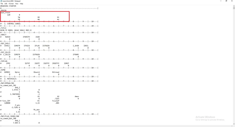
So after finding our unit system to be correct we need to create the appropriate interface, friction 0.2 and recommended parameters.
For this model, we are using Type 7 interface. It is an interface between the master surface and slave nodes. We can also use other interface cards individually or in combination to type 7 as they help to remove intersections and Inacti helps in removing penetrations. Using more cards will increase simulation time but will also improve results. Intersections are when a node penetrates into elements and Penetrations is when a surface with thickness penetrates another surface.
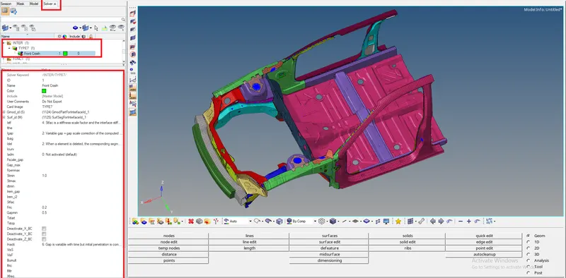
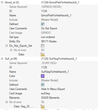
Recommended Values for Type 7 Interface are :
Istf = 4
Igap = 2
Idel = 2
Stmin = 1
Gapmin = 0.5
Inacti = 6
Iform = 2
And for our model, we need to give Fric = 0.2.
Now after setting the interface card we need to check for penetrations and intersections if any. This can be done by opening HyperCrash under Applications. In HyperCrash we need to go in Loadcase - Contact Interface and click this symbol in the image for penetrations and intersections check.
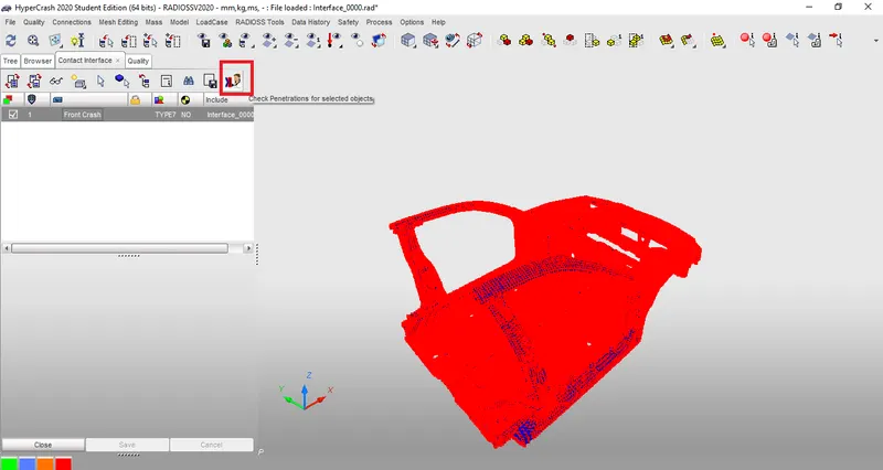
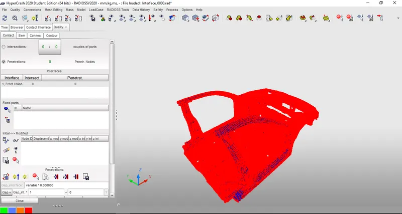
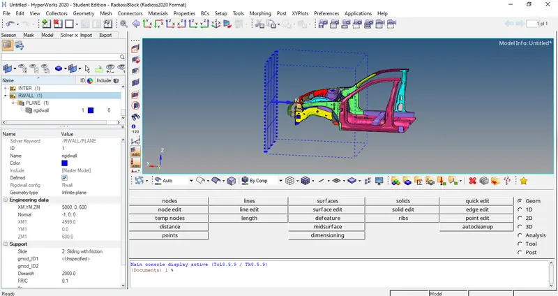
So, for our case, we got no intersections and penetrations. Now we need to correct rigid bodies manually if any. It was not there in our case. Now we will be creating a rigid wall with friction 0.1. This can be done by right-clicking in the solver tab and creating a Rwall of the required type. For this frontal crash scenario, we are using a plane-type RWall.
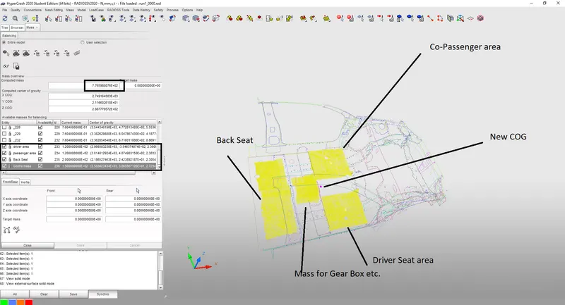
Next, we need to compare the model weight with the full-scale 300k nodes model and use added masses to reach the target weight of 700kg while getting CG about the required range. This can be done in HyperCrash easily. First, we need to check for COG and Computed mass value. This can be checked under Mass - Balancing - Show COG Point.
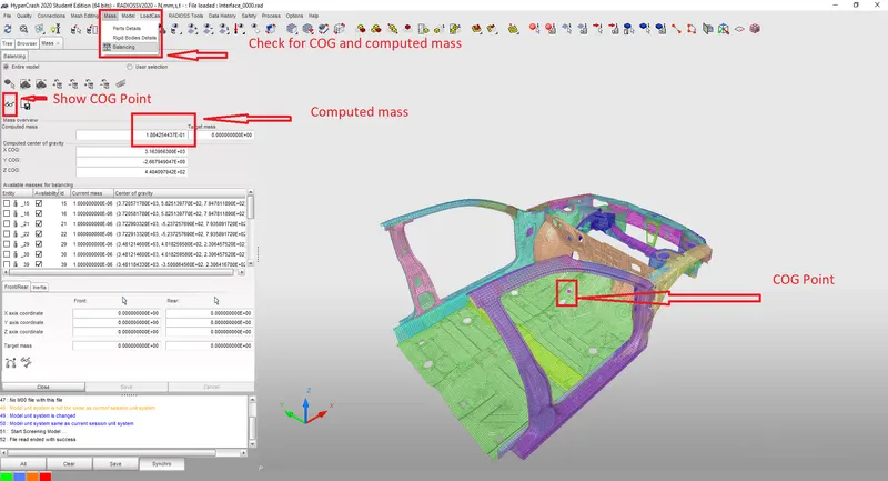
Now we notice here the mass is 188Kg instead of 700Kg. So we need to add mass to nodes in the model in such a manner that it reaches 700kG FOR 300K nodes model and also COG shifts to a position where it should be in a full car model with mass addition. So mass addition is done under
loadcase - Added Mass - Create new mass by right-clicking type 1 where mass is distributed to each node of node group.
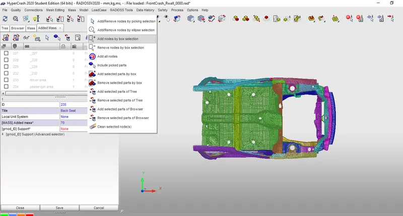
In this we can change the title of added mass and give the mass amount in added mass and in support, we need to provide the node id to which we want to apply mass. For this, we need to right-click and select the area by using add nodes by box selection. And select nodes to which you want to apply weight. So in our case, we added mass at 4 different locations i.e., Near driver seat area indicating weight for seat and driver, Co-Passenger sitting area indicating weight for Co-passenger seat and person, Back seat area, and centre mass indicating weight for gearbox etc. And the values were decided based upon standards for that area.
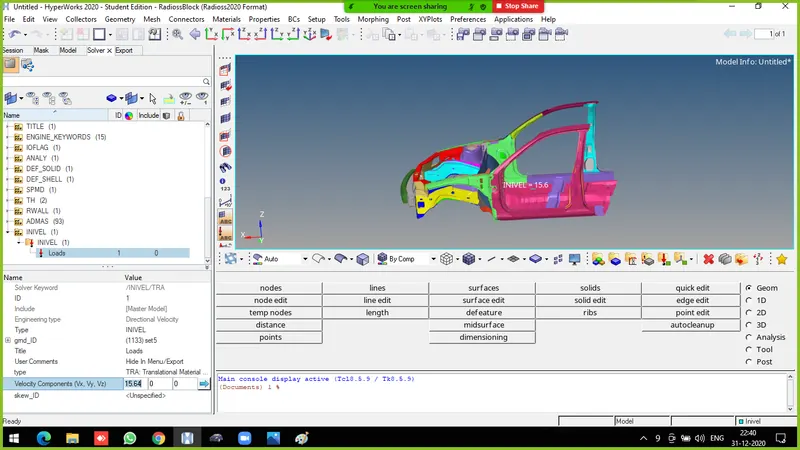
Now we need to set the initial velocity as 35mpH. This is done by creating an INVEL card by right-clicking in the solver tab. And applying it to our model. As our unit system is in mm Kg ms so we need to convert 35mpH to given unit and it comes out to be 15.64mm/ms.
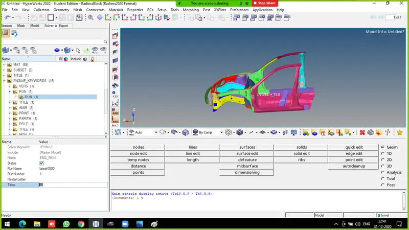
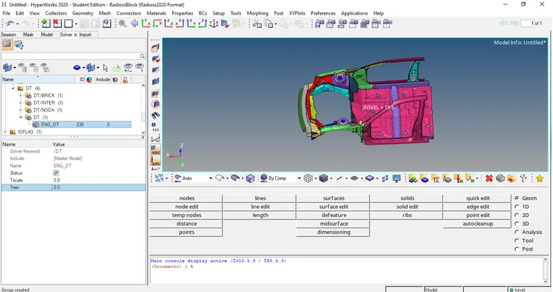
Now we need to change the timestep to 0.5-0.1ms and also Run for 80ms. As both of them are a control file so it will come under Engine Keywords. DT for Timestep and Run for simulation time.
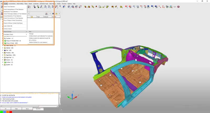
Now all the setting is done now we need to use a model checker to ensure good quality. For this we again use HyperCrash and it can also be done in HyperMesh. This is necessary because while defining things for the model which we did tell now we may make mistakes or we forgets the unnecessary cards to be removed after updating things. So by model checker we will come to know all the errors and warnings for our model. If we have only warnings then our model will easily run and if we have errors then the model won't run. Now how to check this? For this we can check models from both HyperCrash and HyperMesh but we have used HyperCrash here.
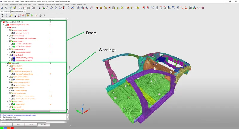
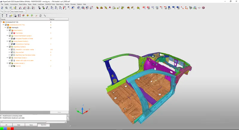
So we got this many errors and warnings for our model now we need to eliminate them very carefully. And never use the autocorrect option as it will ruin all settings and we need to go all steps again. So we usually understand each and every error first and dig the reason why it came. And see if we can correct the same or we usually create that step again. Atlast it should be all warnings no errors and we successfully achieved it.
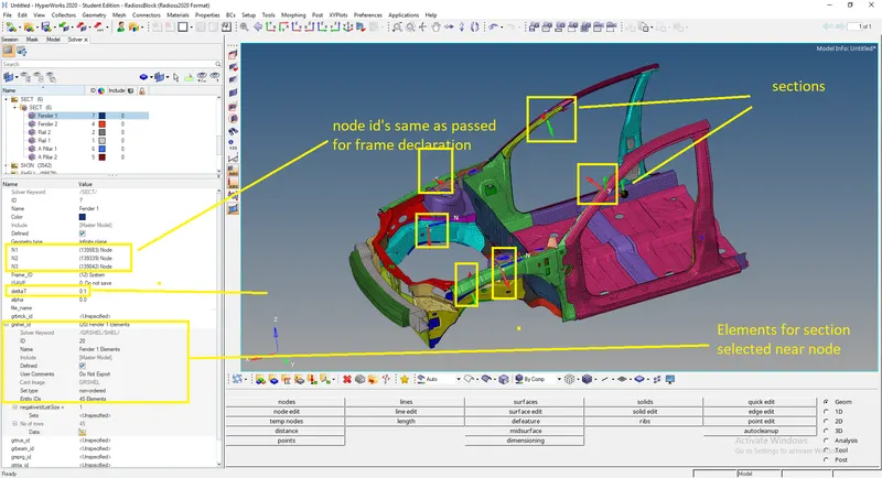
Now the time comes for outputs and analyze things happening to model. We will start with setting the things for getting sectional force in the rails at the location of indicated node 174247. Now this statement itself says that first we need to create a frame of reference for the informed node and later define a section for the same node along which study will be done and to have this in output we need to declare the same in TH (Time history).
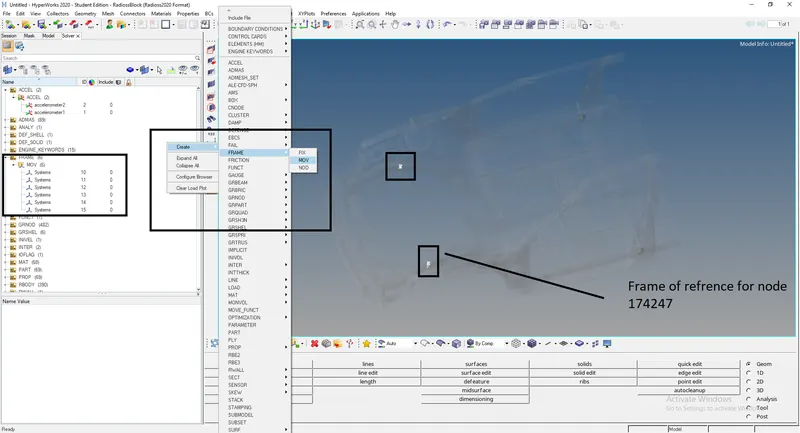
While creating a frame you have multiple methods which need a careful selection of node and axis selection as when you make a section out of the frame the direction of normal or local coordinate i.e. frame, should be in the direction of crash. As we are taking output request with reference to this section only.

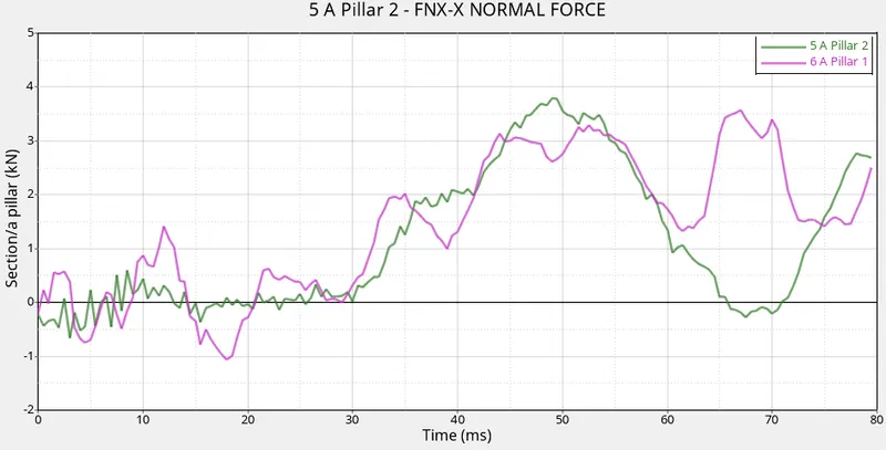
Similarly using the same process we created 6 movable frames 2 for rails, 2 for shotgun and 2 for A-pillar. And later sections were created out of these frames. Section can again be created by right clicking in the solver area and selecting the sect.
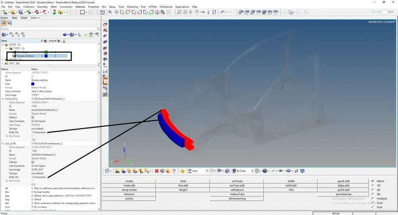
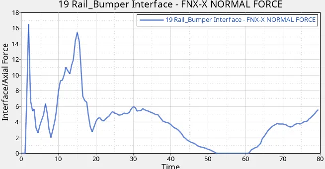
Other than this we need to find axial force received on the rails from bumper. For this we create a interface in between bumper and rails of Type 7 and pass ground id as bumper and surface id as rails.
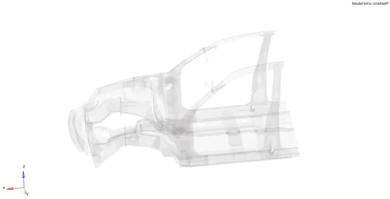
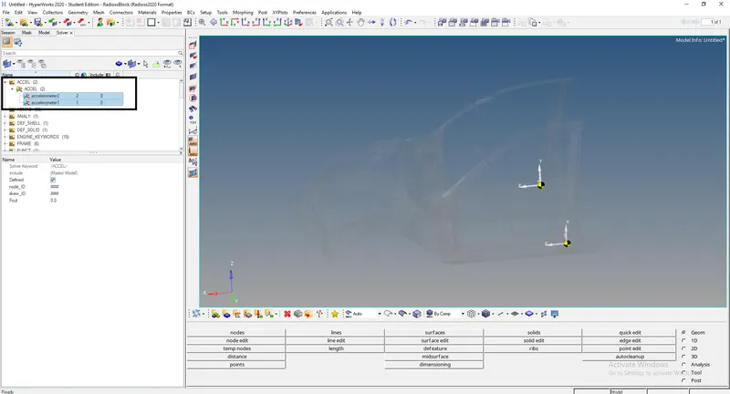
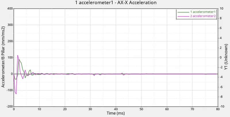
Now we will be finding the acceleration curve received on the accelerometer at the base of B pillar (on B pillar rocker). For this we will first create a Fixed Skew along a node at B-Pillar base. And later will create an accelerometer at the same node defined in skew and to have the same results as output we declare it in TH/ACCEL. The procedure for skew creation is the same as that of frame creation.
Accelerometer is again created by right clicking in the solver tab.
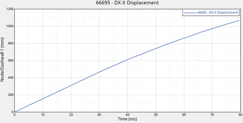
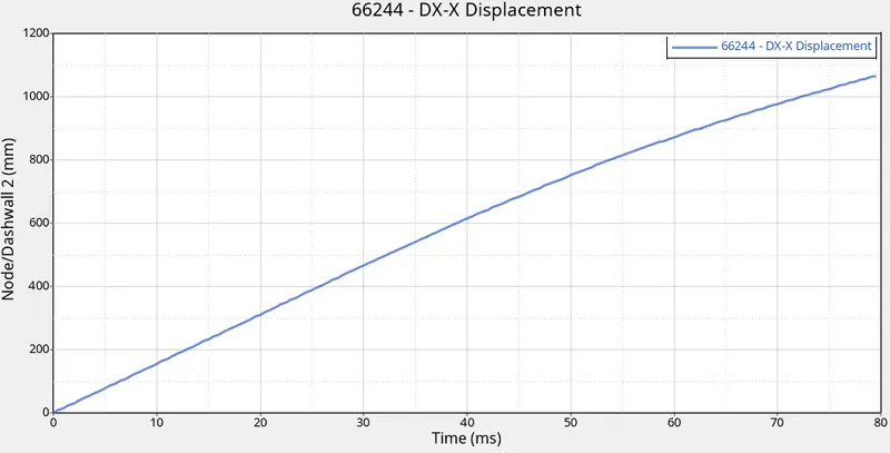
Now the last thing we need to check is intrusions on the dash wall 66695,66244. For this we actually have 2 methods: first we can directly define it under TH/Node or we can do a better approach by creating a spring in between the asked node and a node on the surface which is exactly perpendicular to the asked node. Spring definition has to be done in that case. But the results are much better than TH approach. We are using TH approach here. While defining intrusion we just need to give a node id in entity id in our case.
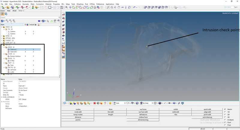
Now all the output request setup is done and we just need to check results for our model now.
Animation File Links:
https://drive.google.com/file/d/1zyIKh23KhYq8k_-xp0skq8f2gNn4P3lI/view?usp=sharing
https://drive.google.com/file/d/1uTihafvxDG-a_JE5xFGY90G7HCvOeIa4/view?usp=sharing
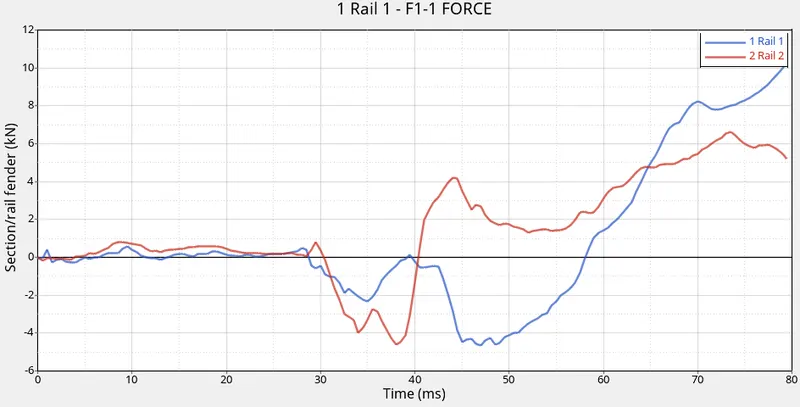
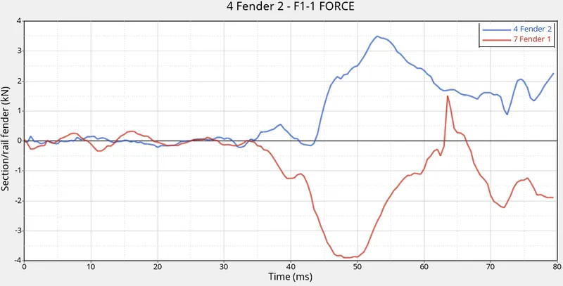
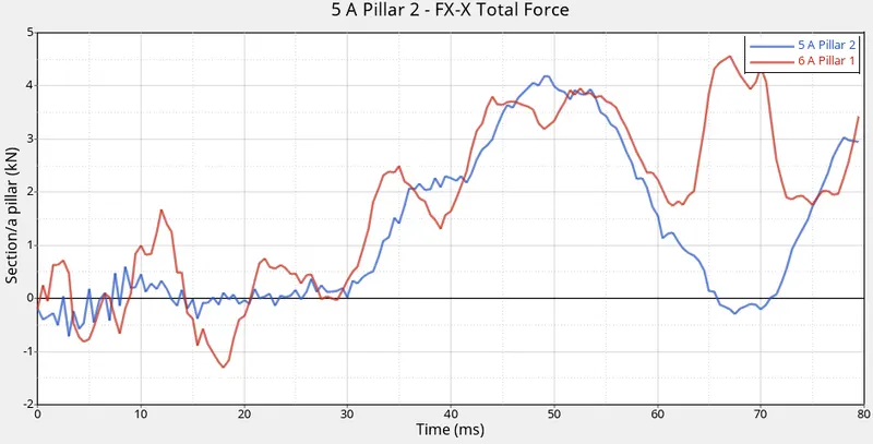
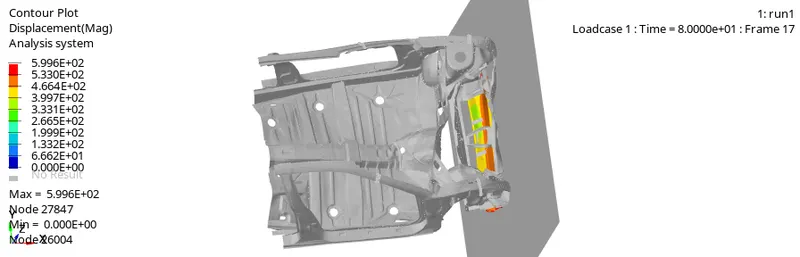
In the results, you will see changes in the curve behavior of rail1 and rail2, and similarly in shotgun1 and shotgun2 and also in A-Pillar 1 and A-Pillar 2. Although we have the very same geometry on both sides and also a full-frontal crash is happening still we experience such plots because of the mass difference on both sides. Rear masses affect changes with time actually, created this difference when they come into solver considerations they start affecting much until then there won't be much of a difference. Also in our case, we shifted the COG of the model to a little towards of driver seat where it should be in an actual car model because of which if we see the animation file clearly we will see with the crash body is tilting more towards the driver side. And this area experience more loading. And all this in all 4 plots of sectional force representation shows after 30ms and during this time von misses stress starts engaging that area very much. And for other plots, we have results as expected and not very questioning. Only in accelerometer testing, we see some plot change due to the same reason of mass shifting to the driver area.
Observed values of mass error and energy error in run1_0001.out file.
Mass Error : In the range of = 0.1283E-01 - 0.1380E-01.
Energy Error : In the range of = 0.0% - (-1.1%). Negative because energy is dissipated during a crash.
These small values of mass error and energy error are in acceptable range so no need to worry about the same.
Model Drive Link : https://drive.google.com/drive/folders/1JhnAEu2SyAZKz71xhUJSiOekQBUP9Qsx?usp=sharing