Assignment 5-RADIOSS Interfaces & Study of Effect of Notches Challenge
Aim: Meshing the provided component and later analyzing results by making several changes in solver configurations.
Procedure: Now, as we know first we need to do mesh on the provided model to make it ready for analysis. And to start with mesh one should always check for geometric errors first in the model. So our first task is to check all the geometrical errors.
So or after checking the model we found several errors majorly like missing connections between edges which can be identified by looking color of edges and making a conclusion on whether it is a single edge, double edge, or triple edge.
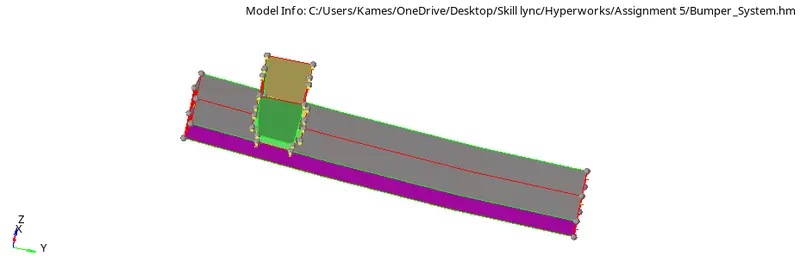
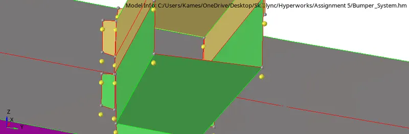
So, to correct this we need to make connections at all required positions. Even we need to provide some 1D connections in it as we have 2 sets of components here and they both are not connected. So to remove the error we can use the option of quick edit in the geometry bar. And in quick edit, there is an option called toggle lines. So we can use this option to connect edges by providing a true tolerance value in it.


After doing all geometrical error model will look like this.
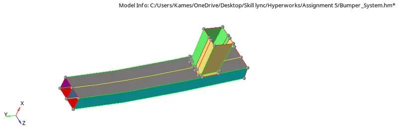
Now the remaining portions have to be provided 1D connections but before that, we can do meshing on it as the model is now ready for meshing. So as this is a sheet metal body component so we need to do 2D mesh in it and if it would have some meaning full-thickness then we would have done 3D mesh.
So, in the 2D mesh panel, we have the option of auto mesh in which we will set few parameters and later run the command for meshing.

So these are the requirements we came up with for analyzing this component. The mesh type is quad only as a quad is better than tria when analyzing component as it is seen tria leads to several quality errors. So while meshing in Hypermesh one has to take care of a thing i.e. keeping the numbers the same on opposite edges to have only quads on surfaces.
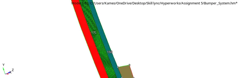
As we have different numbers here i.e. 168 and 170 so it is seen it leads to the formation of trias or rotating quads. And if we make it 170 -170 on both edges than it will be a good mesh generation.
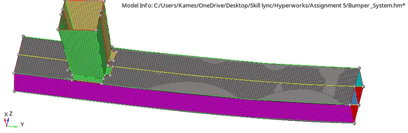
Now the only thing to be done is of providing 1D connections i.e. of spot weld at all required positions. So for this, we need to move in the 1D panel and in that we can choose the option of connectors and in it seam weld. So in this, we will make several changes as per requirements and select correct pairs of nodes and surfaces to create seam welds.
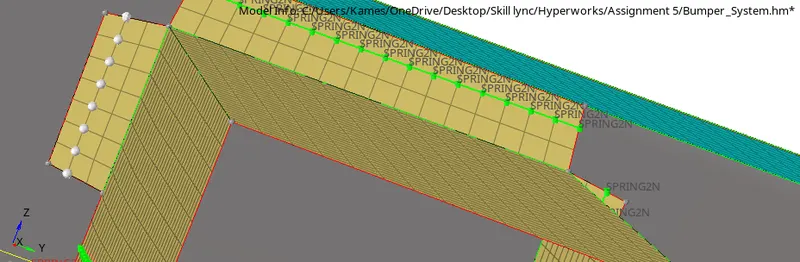
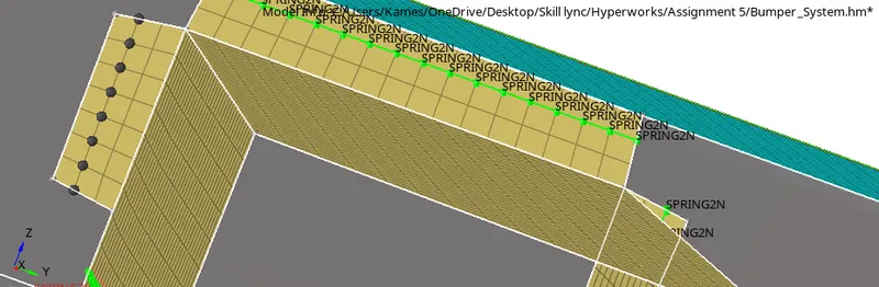
So like this, we provided seam weld at all the required positions and it can be easily identified by seeing SPRING2N on several nodes along edges.
This way our first task of meshing the component is done now we need a starter and engine file for this component to analyze the model. So it was provided to us already.
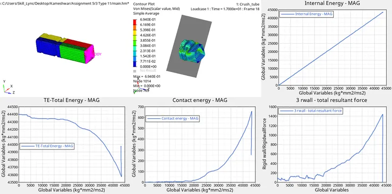
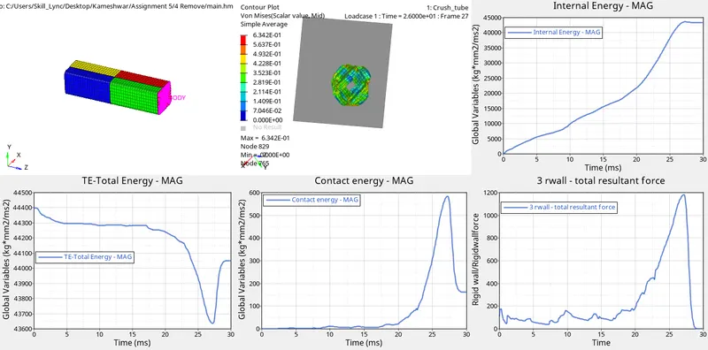
So here we will see multiple cases of analyzing the same component by making changes in solver configurations at every step and even changing geometry and noticing changes in results in all cases.
There will be a common process in all different cases that will be after making all required changes in solving configuration and model geometry one should go to analysis panel and in it Radioss. There we need to save every time in a different folder that defines that state for the model and later run it and check results.
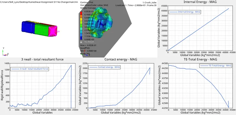
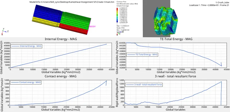
So as for our first cases, we will run the model as it is by not making any changes in the geometry of the model and not changing any model and solver properties. Keeping Interface type to be type7 and Inacti as 0 means multi-usage impact interface, modeling contact between a master surface and a group of slave nodes.
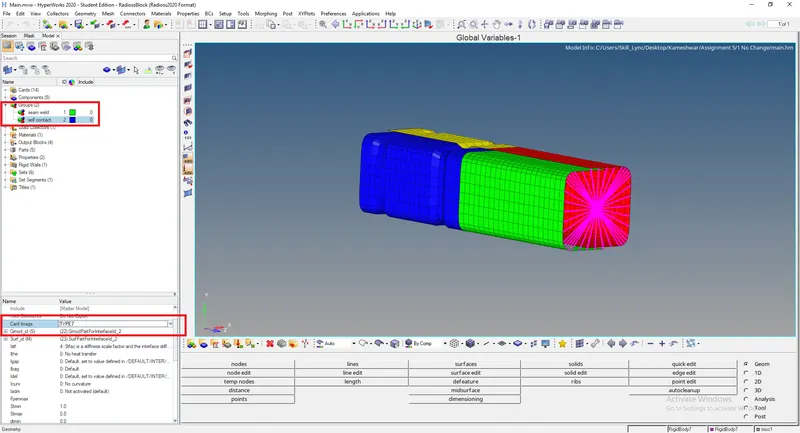
So initially we had a Type 7 contact defined for our model with Inacti as 0. This means an interface has been set up between a master surface and slave nodes with no special treatment for penetrations. The results we found for same are:
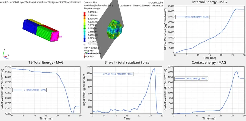
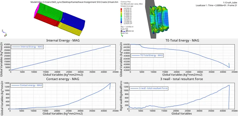
The next thing we need to do is change Inacti to 6 in the same card and see how it changes results. Here inacti as 6 means the gap is variable with time, but the initial gap is adjusted as (the node is slightly depenetrated):


Refrences :