Week-6 Calculate the Stretch Ratio by comparing the ELFORM (-2,-1,1,2) with Ogden_Material Model.
Aim:
Conduct a simulation of stretching the cube of 10mm*10mm*10mm with the given material properties and find the stretch ratio by comparing the different element formulation using Ogden material.
Objective:
- Create a cube of length, breadth and height of 10mm with the elements of length 1mm.
- Attach the given material card and apply to the cube elements.
- Apply the required boundary conditions and load to the cube.
- Attach the required control cards and define the load steps and termination time.
- Obtain the required results and validate them. Compare the results for different element formulations.
Theory:
The material being used here is Ogden rubber material which is hyper-elastic in nature. Displacement load will be applied and the material will undergo elongation in a quasi-static manner. So for the analysis, the implicit method will be employed.
Stress and strain from the simulation will be the true stress and true strains of the elements.
- True strain = ln(1+ Engineering strain)
`=>epsilon_T=ln(1+epsilon)`
`=> e^(epsilon_T) = 1+epsilon`
- Stretch ratio=final length /initial length
`***=>lamda = l_f/l_i =(l_i+delta)/l_i`
`=>1+delta/l_i`
`=>1+epsilon`
`=>therefore lamda=1+epsilon =e^(epsilon_T`
- Nominal stress (Engineering stress) = true stress/ stretch ratio.
`sigma_n= sigma_t/lamda`
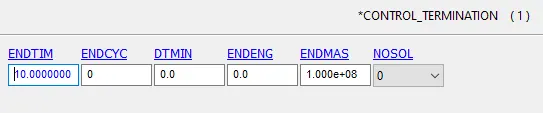
A displacement of 30mm will be applied to the model and the model will be simulated under the implicit method. Different element formulations for the solid elements are compared.
Procedure:
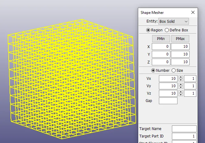
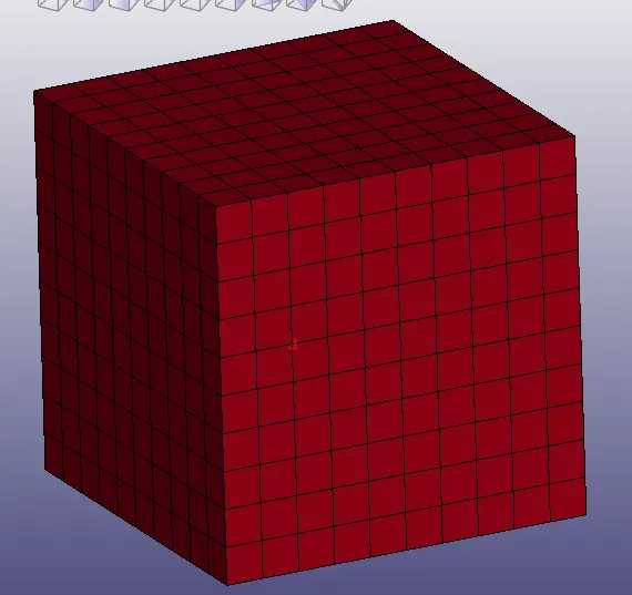
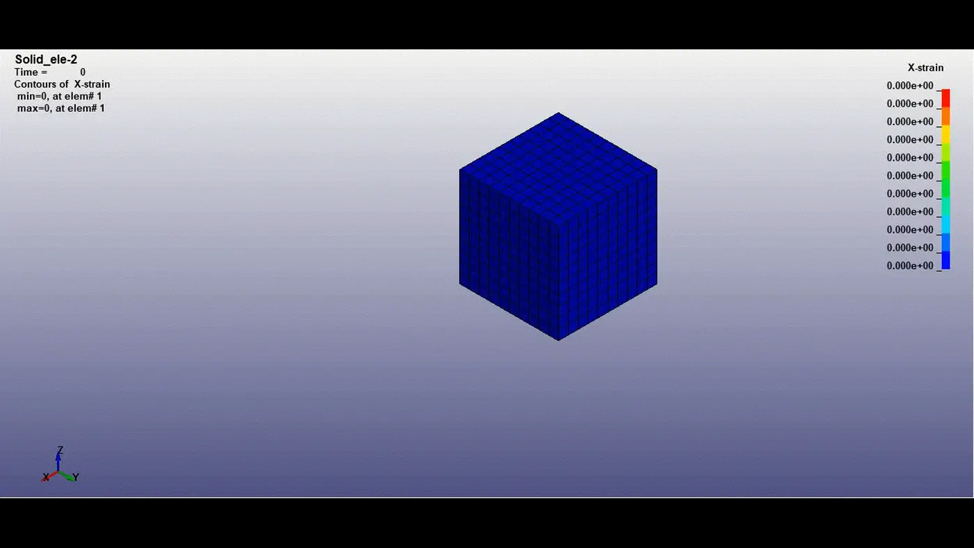
- A box of 10mm*10mm*10mm is created from Shape Mesher with each element having a size of 1mm with an entity as Box Solid as shown below.
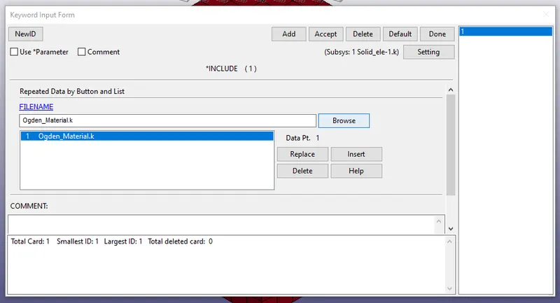
- Insert the hyperelastic Ogden material card through Include keyword from the keyword manager tab.
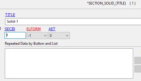
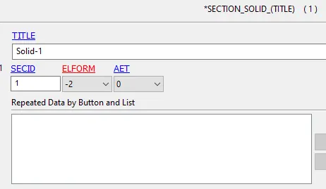
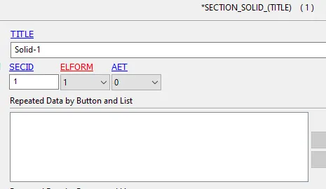
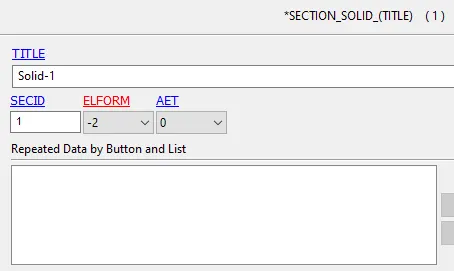
- Solid Section with different element formulation is created for each simulation.
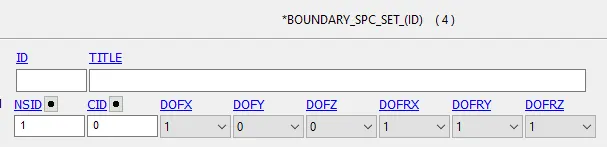
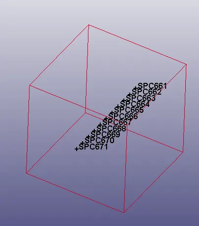
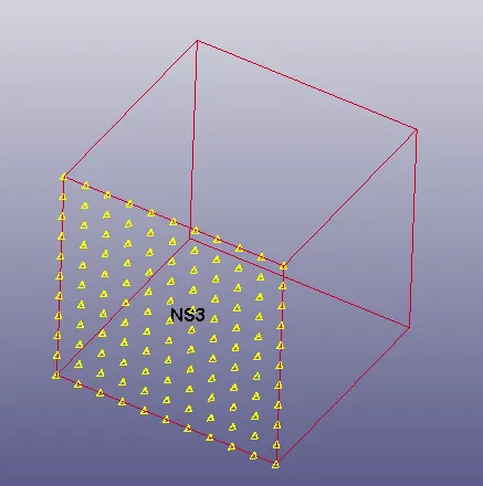
- SPC constraints are applied on one face of the box as shown. Boundary conditions are applied to induce stability to the model. The model is allowed to expand in x-direction.
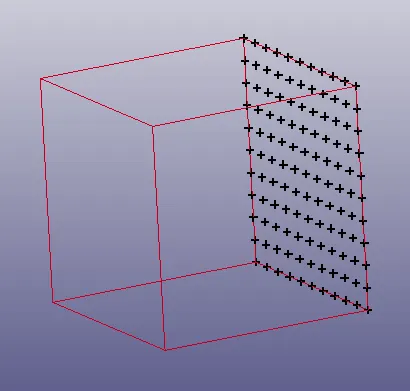
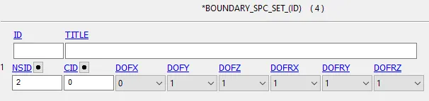
- Being the hyperelastic material, the model will contract aggressively and might cause an error. So, to induce stability more boundary conditions are included in the model.
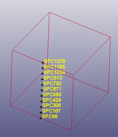
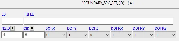
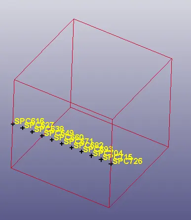
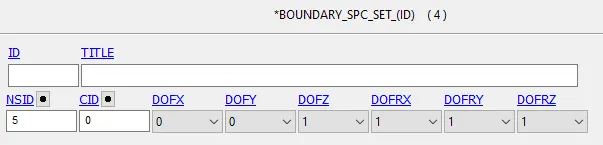
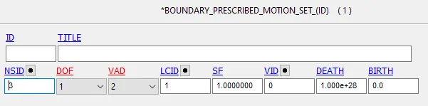
- With Define keyword, steady displacement load curve of 30mm is defined.
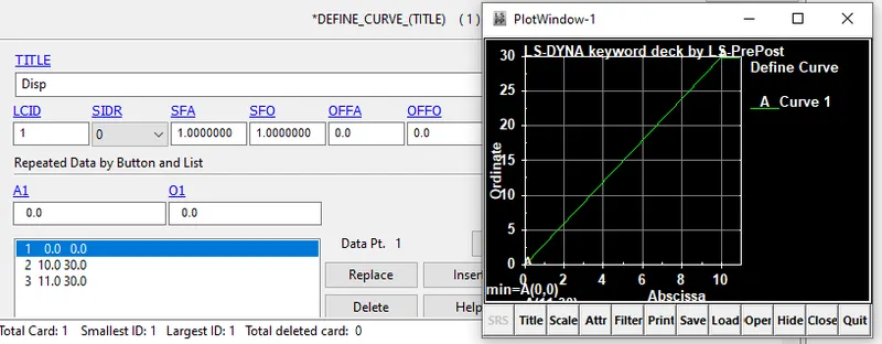
- Prescribed_motion is applied to the nodes on the other face, such that the model will undergo uniaxial tension.
- Required control cards like termination, implicit cards are defined as follows.


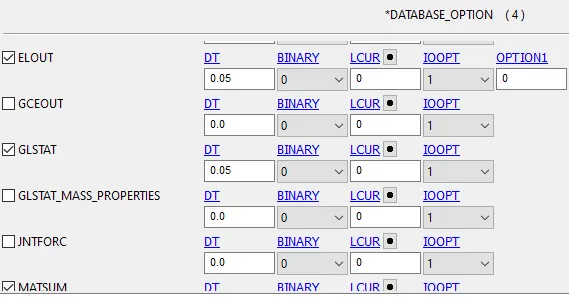
- Required database requests is keyed in to obtain the results. STFLG in Database_extend binary cad is kept to "1" so that the strain tensors will be written.
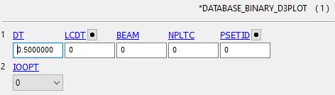
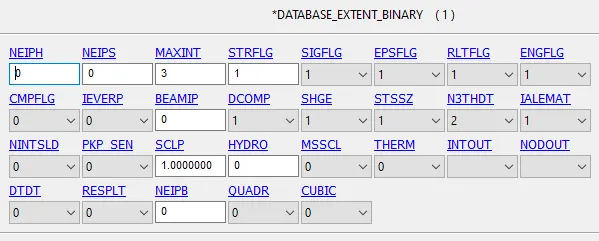
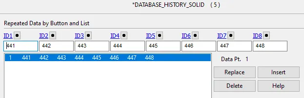
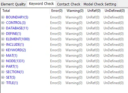
- The model is checked for errors and then simulated.
- On successful termination of the simulation, the results will be verified and then compared.
Note:
element of ID 550 is considered for the element history plots.
- Case 1: Ogden material with eleform=1. Constant stress solid element.
- Case 2:Ogden material with eleform=2. Fully integrated solid element.
- Case 3:Ogden material with eleform=-1.Efficient formulation of a fully integrated solid element.
- Case 4:Ogden material with eleform=-2. Accurate formulation of a fully integrated solid element.
Results:
- The given displacement is 30mm in the X-direction.
`delta =30mm=>epsilon = delta/l_i>->>epsilon = 30/10=3`
`but, 1+epsilon = lamda=> therefore lamda=1+3=4`
`"So, stretch ratio"(lamda)" in x-direction is almost equal to 4"`
Graphs-
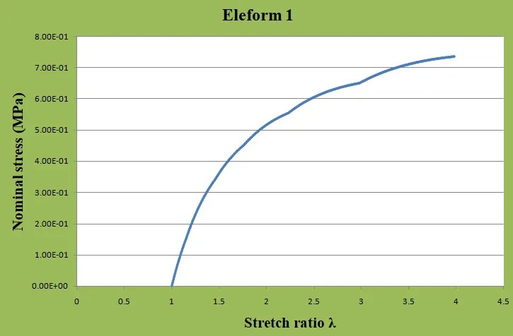
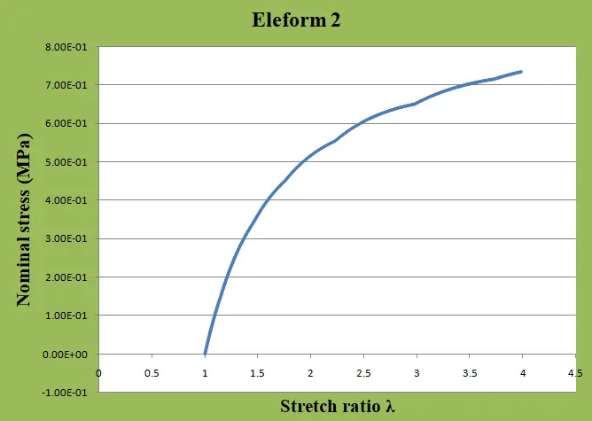
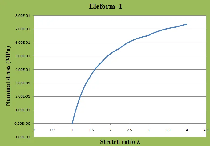
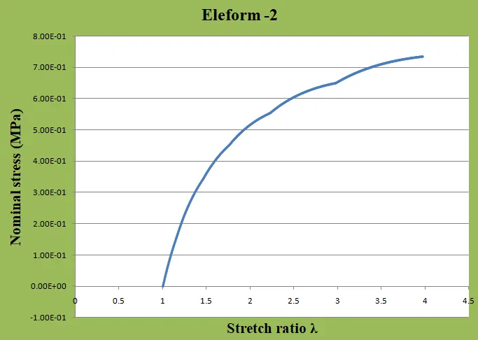
The graphs between the nominal stress and the stretch ratio extracted from the output results from each case. It is found to be the stretch ratio in all cases is almost equal to 3.97 which very close to the expected value for the displacement of 30mm.
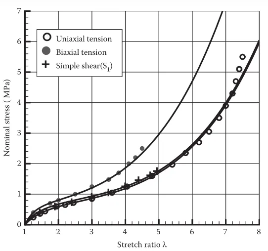
The graphs from all 4 cases match with the above reference curve in uniaxial tension loading till the maximum stretch 4 i.e, for the displacement of 30mm.
Stress:
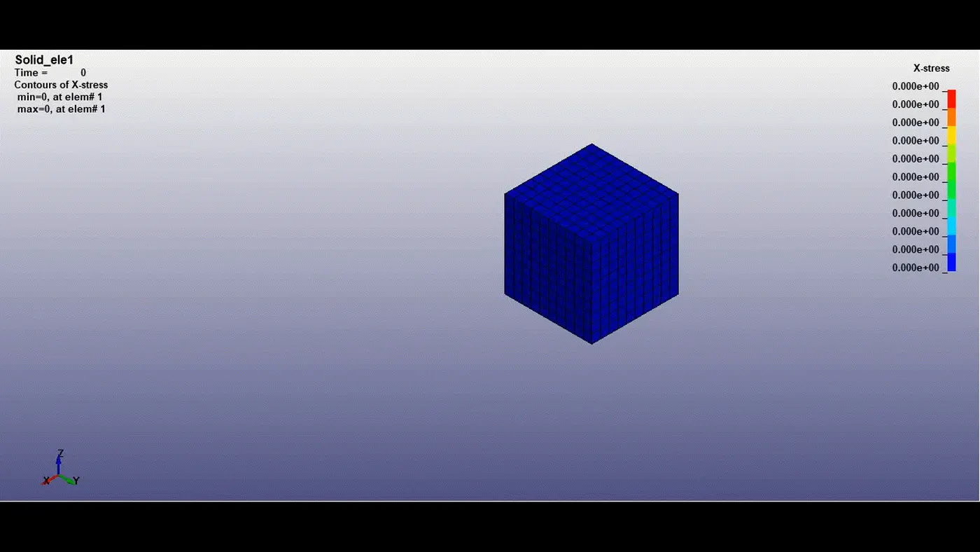
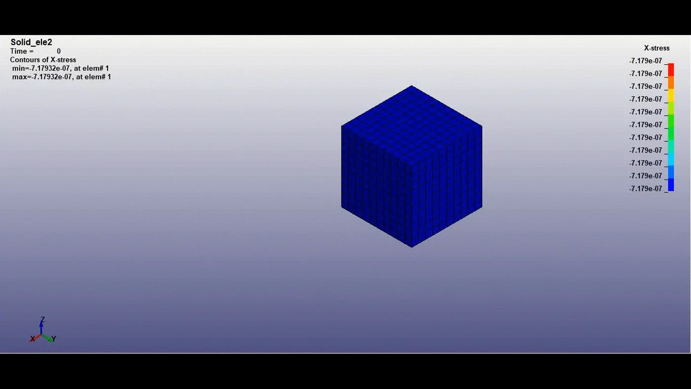
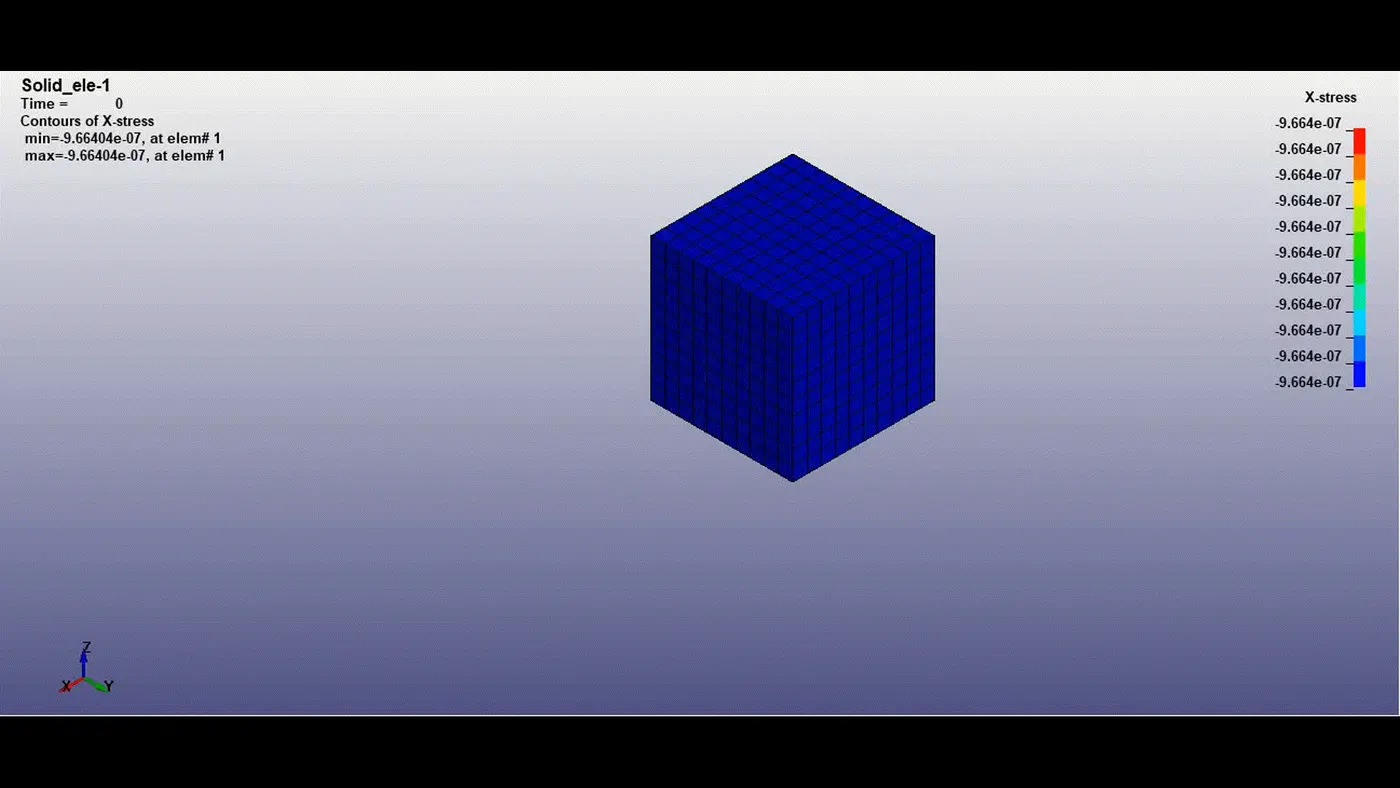
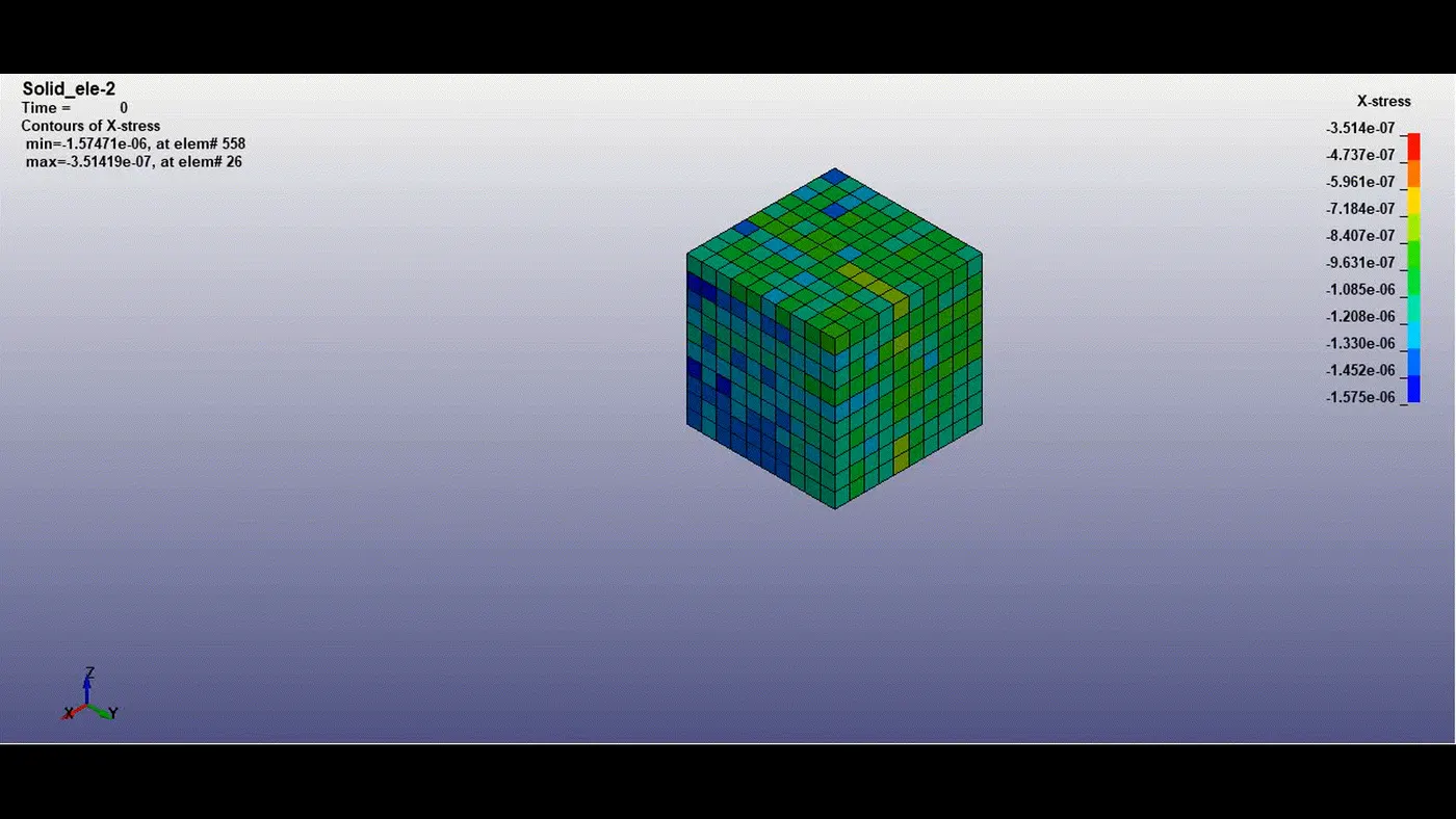
From the simulation, the above model with Ogden material stretches and gives a stable response of elongation mostly in the direction of displacement (i.e load in X-direction).
| Von-mises stress (Max, MPa) | X-stress (Max, MPa) | |
|---|---|---|
| Case 1 | 2.9316 | 2.9339 |
| Case 2 | 2.9265 | 2.9252 |
| Case 3 | 2.9269 | 2.9264 |
| Case 4 | 2.9314 | 2.9279 |
Strain:
| Effective strain (Max) | X- strain (Max) | |
|---|---|---|
| Case 1 | 1.2913 | 1.3853 |
| Case 2 | 1.2904 | 1.3815 |
| Case 3 | 1.2906 | 1.3818 |
| Case 4 | 1.2904 | 1.3810 |
Conclusion:
- The result from the simulation in all four cases i.e., with different solid element formulations matches the calculated stretch ratio values.
- The response of the ogden material with different element formulation yeilds almost same results, thus element formulation in the above case doesn't have significance role. Therefore reduced element formulation can be used for the solid elements to increase efficiency.