Week 1 Spur Gear Challenge
Aim:
Conduct a structural analysis to find the equivalent stress, deformation and stress intensity on the spur gear. Carry out the simulation with ductile cast iron, cast steel and cast bronze as material and compare the results.
Objective:
- Start the structural analysis and update the engineering data with the required materials along with the properties.
- Import the geometry of the spur gear into the analysis system and apply the appropriate materials to the gear objects. Contacts between the spur gears with each other are defined
- Two revolute joints, one for each gear object is defined and generate a mesh with appropriate element size.
- Analysis requirements like analysis settings, load conditions and output requests are inserted and solve the model.
Theory:
Gears are generally used to transmit the rotation motion from one system to another system and help in power transmission. Using gears of different sizes can achieve gear reduction also. Spur gears are the common type of gears used to transmit power between two parallel shafts.
Procedure:
- The structural analysis system is activated into the project schematic and engineering data is prepared.
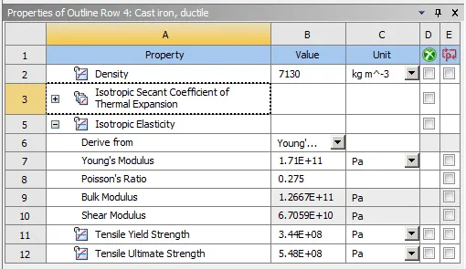
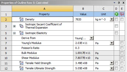
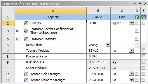
- Ductile cast iron, cast steel and cast bronze material properties are added to the engineering data.
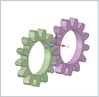
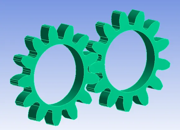
- The spur gear model is imported into the model tab and is opened in space claim. Gear geometry is checked and updated into the model tab.
- Model is opened in mechanical module and material is applied to both gears.
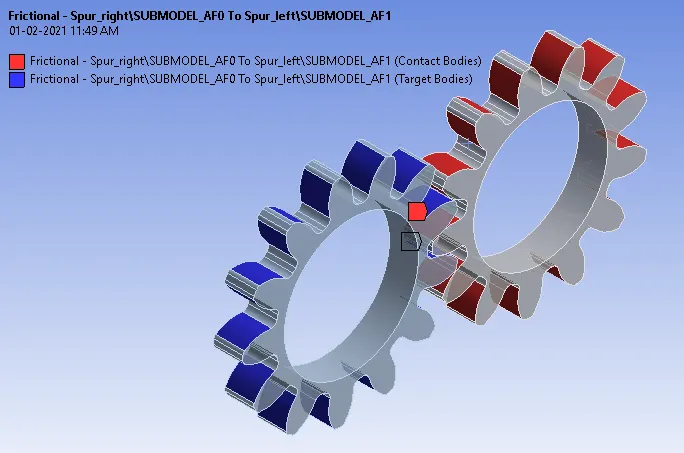
- Frictional contact with appropriate contact and target surfaces from the two gear bodies is defined. Augmented Lagrange formulation with symmetric behaviour and other appropriate definitions are defined.
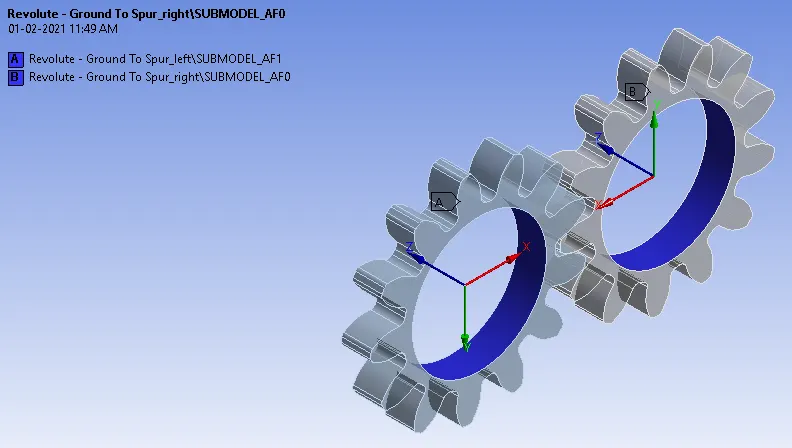
- Revolute joints with inner faces of the gear bodies as scope are defined. Body - ground connection type with revolute joint type is defined.
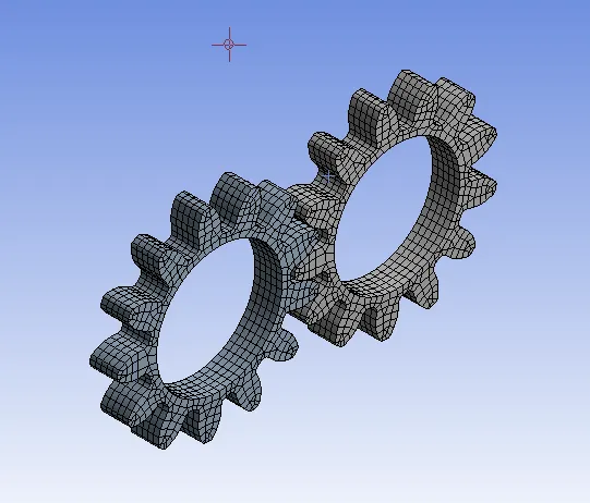
- Mesh of element size 1mm size is used and the mesh is generated.
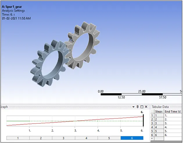
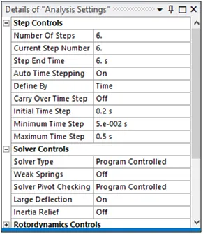
- An appropriate analysis setting with 6 steps has opted and large deflection is allowed.
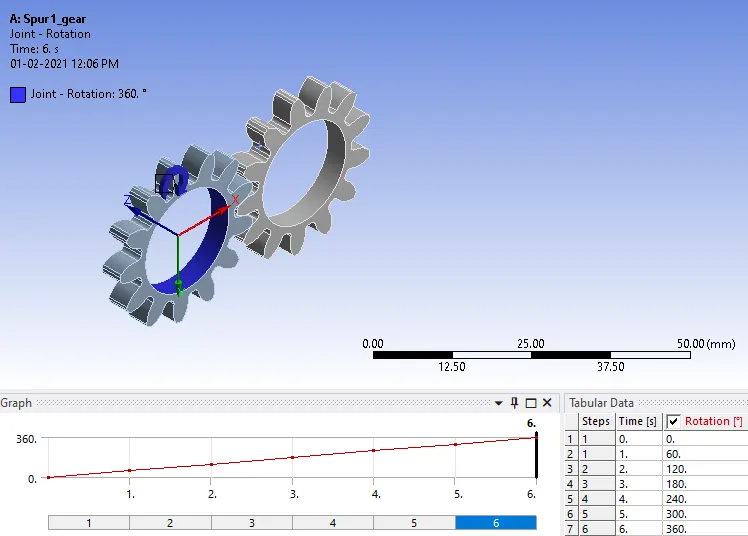
- Rotation load is applied to the one of the gear body (say gear 1) with an increment of 600 for each step.
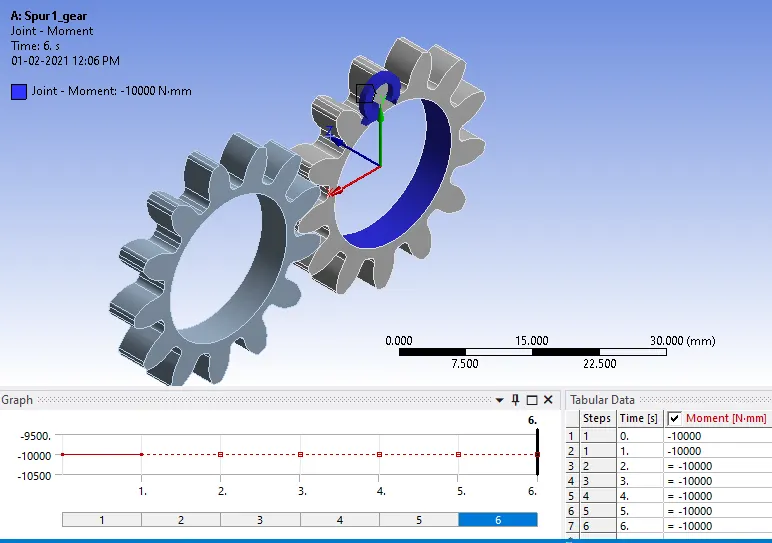
- Moment load with appropriate direction is applied to the other gear body (say gear 2) with -10,000 N-mm for all 6 steps.
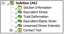
- Appropriate output requests are selected and the model is solved.
Case 1: Spur gear with ductile cast iron as a material
Case 2: Spur gear with cast steel as a material
Case 3: Spur gear with cast bronze as a material
Results:
The solution is successfully achieved for the
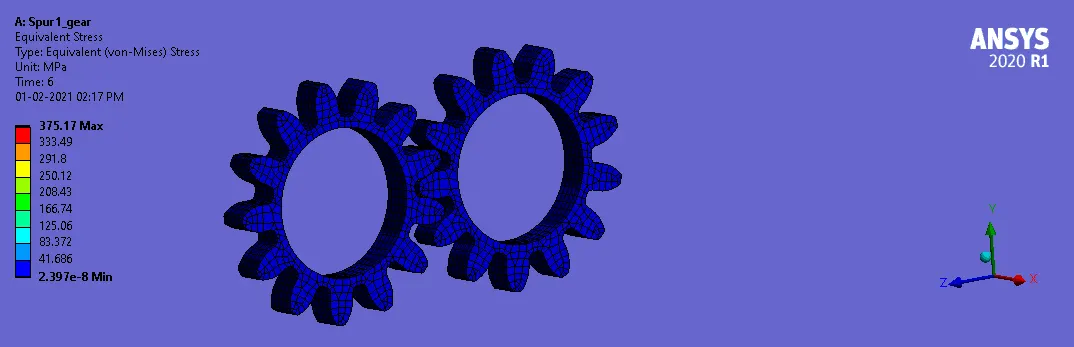
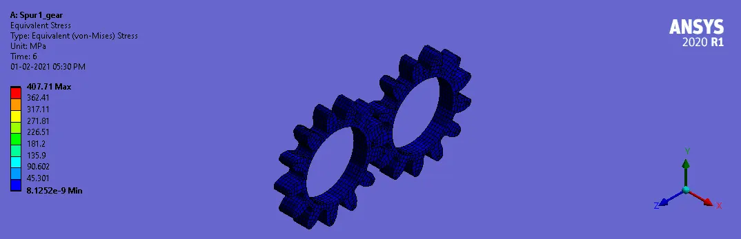
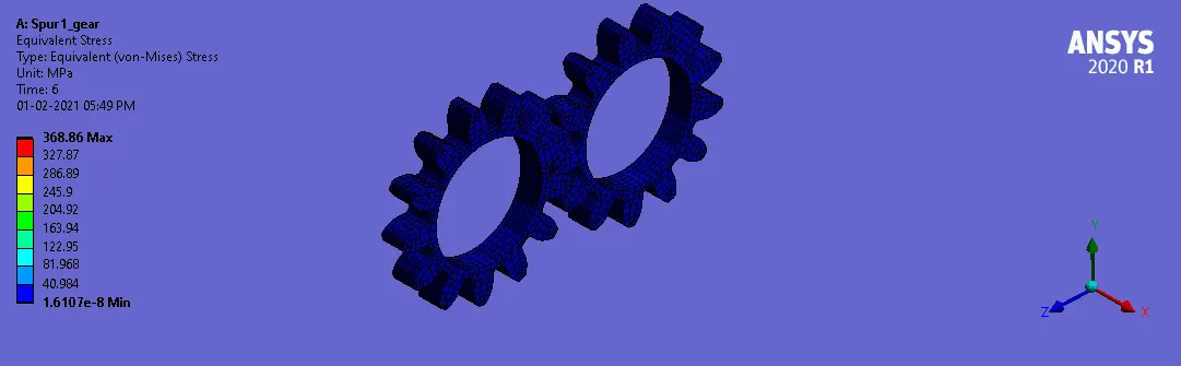
Equivalent (Von-Mises) stress:
case :1
case :2
case :3
| Material | Maximum equivalent stress (MPa) | Minimum equivalent stress (MPa) | |
|---|---|---|---|
| Case 1 | Ductile cast iron | 375.17 | 2.4e-8 |
| Case 2 | Cast steel | 407.71 | 8.13e-9 |
| Case 3 | Cast bronze | 368.86 | 1.61e-8 |
Maximum von-mises stress is observed in the case of the spur gear with the material as cast steel.
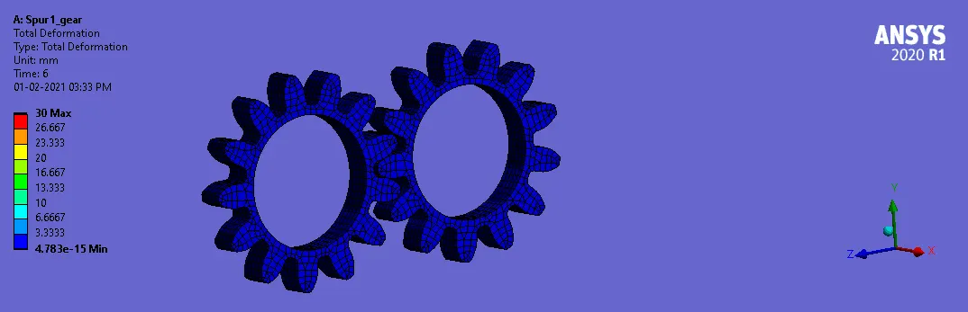
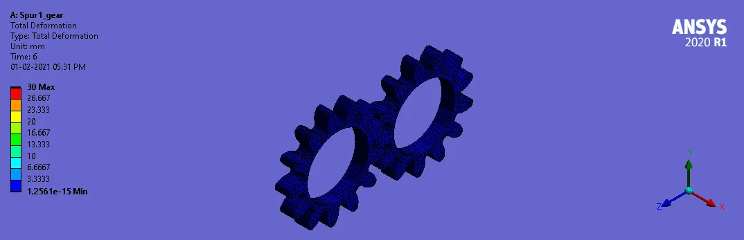
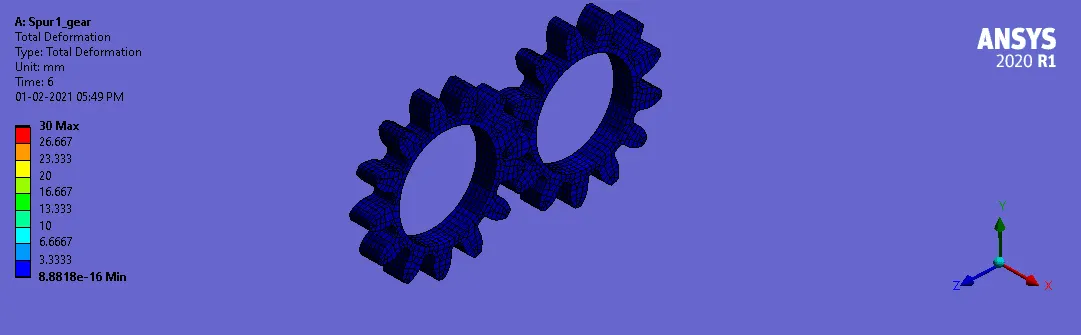
Total deformation:
case :1
case :2
case :3
| Material | Maximum deformation (mm) | Minimum deformation (mm) | |
|---|---|---|---|
| Case 1 | Ductile cast iron | 30 | 4.78ee-15 |
| Case 2 | Cast steel | 30 | 1.26e-15 |
| Case 3 | Cast bronze | 30 | 8.88e-16 |
Relatively all materials produce almost same amount of total deformation for the given load conditions.
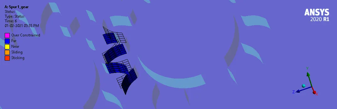
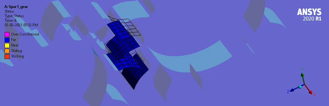
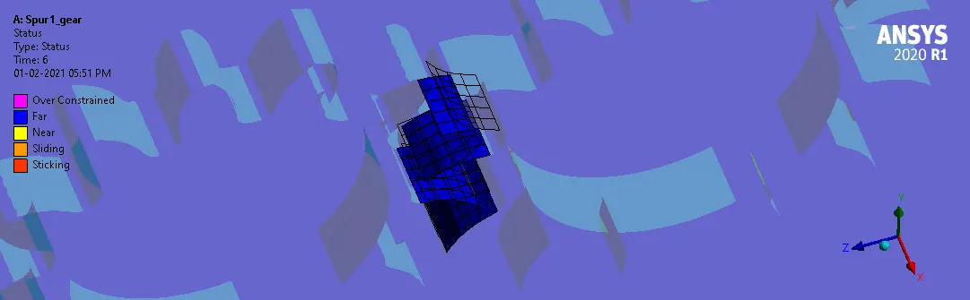
Contact status:
case :1
case :2
case :3
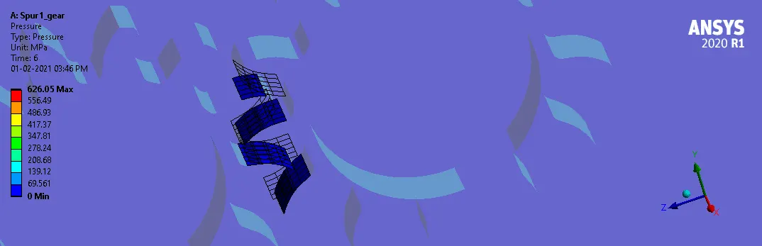
Contact pressure:
case :1
case :2
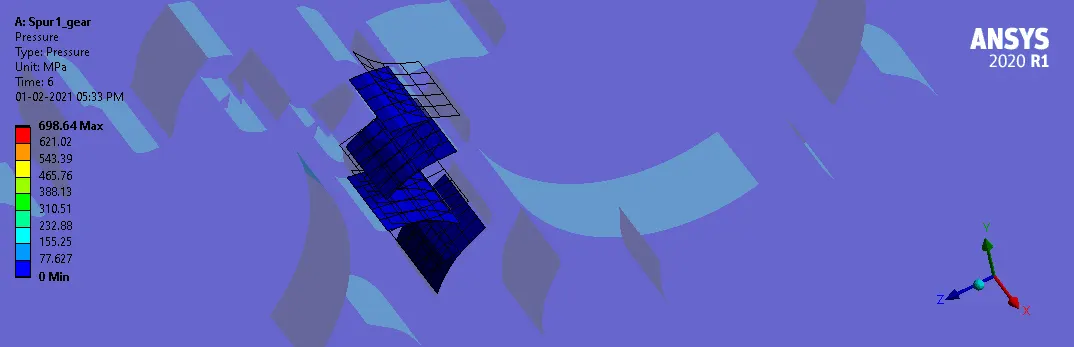
case :3
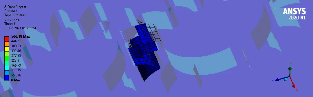
| Material | Maximum contact pressure (MPa) | Minimum contact pressure (MPa) | |
|---|---|---|---|
| Case 1 | Ductile cast iron | 626.05 | 0 |
| Case 2 | Cast steel | 698.64 | 0 |
| Case 3 | Cast bronze | 500.18 | 0 |
Among the three materials, the cast steel undergoes maximum contact pressure while cast bronze experiences lowest of the contact pressure.
Linearized stress intensity:
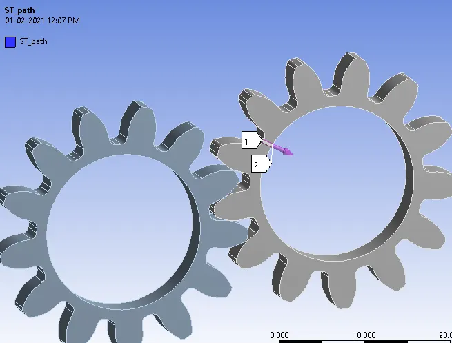
The stress intensity is a concept in fracture mechanics that is used to measure the stress concentration at a crack tip. This is an inherent property of the material that is tested and defined for cracks and flaws. Assuming a path, the stress intensity is obtained for the different materials.
| Material | Maximum stress intensity (MPa) | Minimum stress intensity (MPa) | |
|---|---|---|---|
| Case 1 | Ductile cast iron | 5.248 | 3.614 |
| Case 2 | Cast steel | 5.485 | 3.857 |
| Case 3 | cast bronze | 6.274 | 4.289 |
From the stress intensity values, when crack is present, the model with cast bronze is more likely to get damage compared to the other materials.
Conclusions:
The simulation of the spur gear under rotational load is succesfully completed and the force convergence in all cases were achieved accordingly.
For the same load conditions, cast steel undergoes more stress comapred to the others but while crack is present, due the higher stress intensity the cast bronze is more likely to get failure easily among these three materials.