Week - 5 - Modelling Spotwelds
Aim:
Conduct a crash simulation of two brackets connected with spot welds onto a stationary rigid wall with appropriate material and contact definition. Solid and beam element formulation for the spot weld is characterized.
Objective:
- Prepare the deck for crash simulation of a two brackets connected with spot welds onto a rigid wall with initial velocity of 50kmph given to the brackets.
- Assign elastic and spot weld material cards to the shell and spot weld elements.
- Assign the failure conditions to the spot weld elements.
- Validate and compare the results obtained from the above simulations.
Case 1: Model with beam element formulation for spot welds.
Case 2: Model with solid element formulation for spot welds.
Case setup:
- Import the mesh model of two brackets with shell elements. gm-mm-ms unit system is used in the simulation.
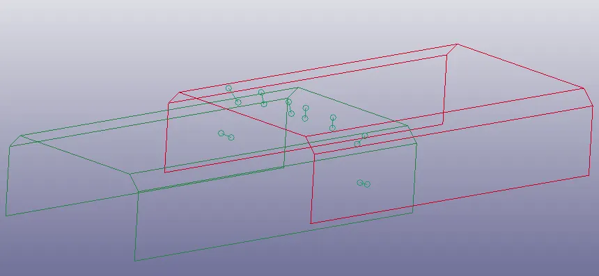
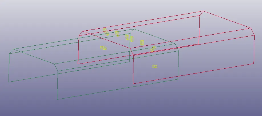
- Spot weld connections are created with beam and solid elements in a symmetric manner in separate files as follows.
Beam element:
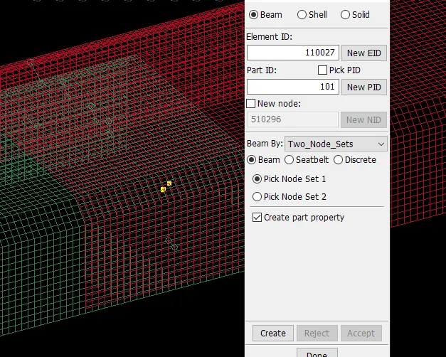
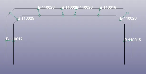
Beam elements are created from element generation tab in element and mesh module with node set selection method. new part ID is given and all the beam elements are kept in the same part ID. Spot weld beam elements are generated in symmetric manner.
Solid_Hexa element:
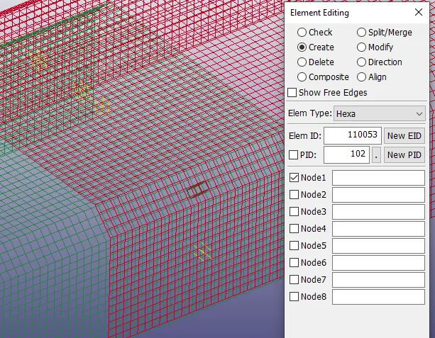
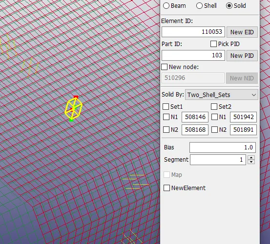
Solid elements can be created from two methods.
- Element editing tab in element tools module:
In this method, nodes all eight nodes are selected in right manner to obtain an element with good orientation i.e. node 1-4 from one shell and node 5-8 from the other shell.
- Element generation tab in element and mesh module:
In this method, shell sets are selected to connect with solid elements and N1 and N2 in both shells are selected to represent the orientation of the solid element.
In both solid element generation ways, solid elements are created in a symmetric manner.

- Material cards are defined as follows.
Elastic-MAT001:
MAT_ELASTIC card is used with steel properties. The elastic material card is assigned to the parts with shell elements i.e. two brackets.
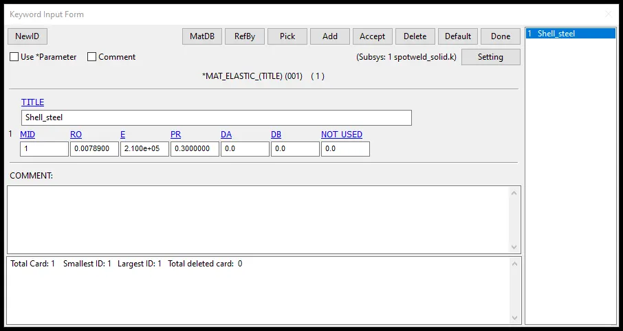
Spot weld-MAT100: this require beam of type 9 and solid type 1 elements to be functional.
MAT_SPOTWELD card is used with steel properties. Spot weld material card is assigned to spot weld elements i.e. beam or solid elements that are created to connect the two brackets.
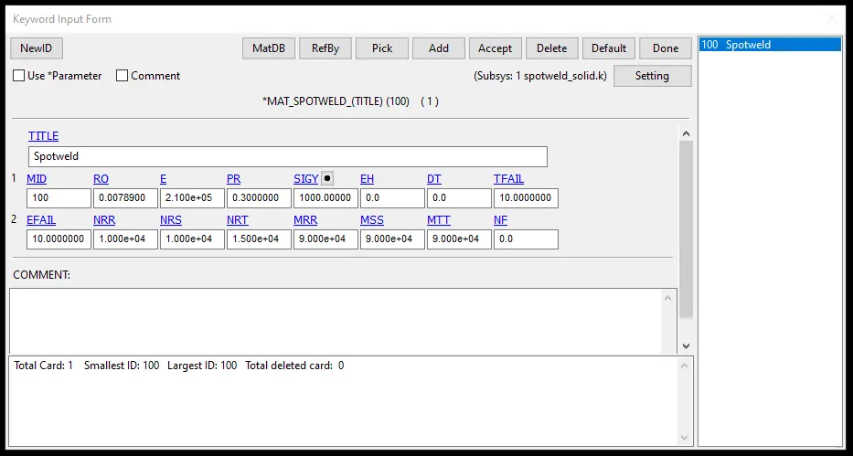
In the above spo tweld material card, the failure conditions can be defined in various approaches. As the element reaches the specified value in the failure definition, the element will be deleted.
TFAIL: Failure time.
EFAIL: Effective plastic strain at failure.
NRR: Axial force resultant or maximum axial stress at failure.
NRS: Force resultant or maximum shear stress at failure.
NRT: Force resultant at failure.
MRR: Torsional moment resultant at failure.
MSS: Moment resultant at failure.
MTT: Moment resultant at failure.
In reality, each element undergoes different forces and moments at various time intervals under loading with respect to their location and orientation. Only critical elements with higher deformation will be damaged in reality and to represent this damage the weld elements at that region will be deleted in the FEA model by using the failure definition. So to calibrate all the elements to fail exactly at half of the termination time, time based failure (with 10 ms as TFAIL value) approach is taken. To avoid failure by any other mode, as a safety measure higher values are assigned to the other failure options.
- Section cards are created and assigned to the parts accordingly.
Shell:
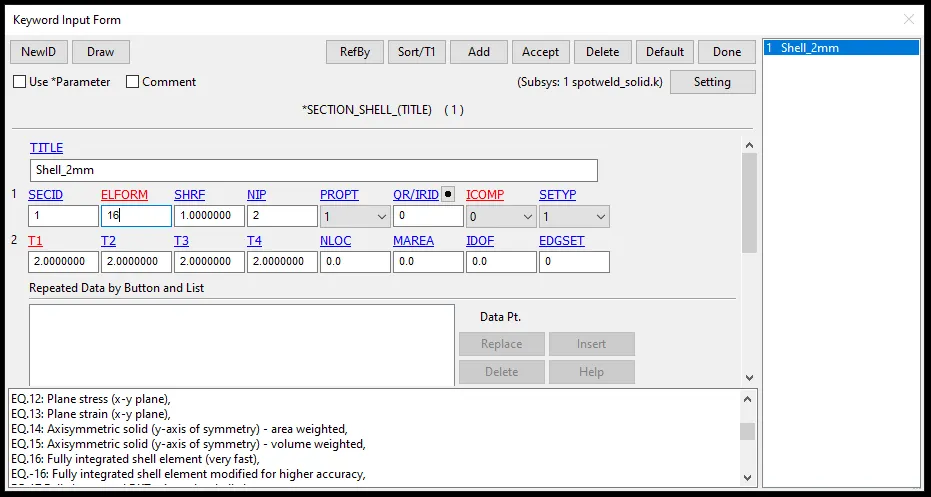
Shell section card is defined with ELFORM of type 16 i.e. fully integrated shell element formulation and thickness of 2mm is assigned to the bracket parts.
Beam:
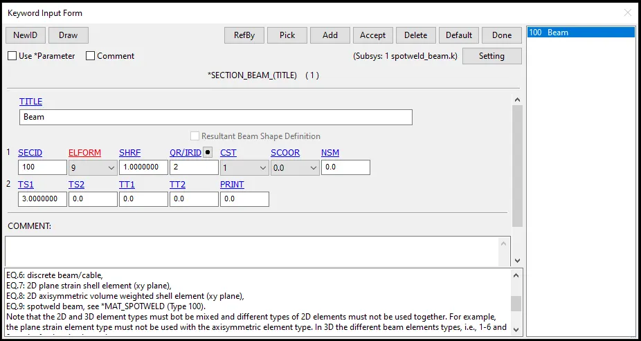
Beam section with type 9 ELFORM for spot weld elements is used. Tubular cross section (CST: 1) with 3mm outer diameter is assigned to the beam elements i.e. spot weld elements in case 1.
Solid:
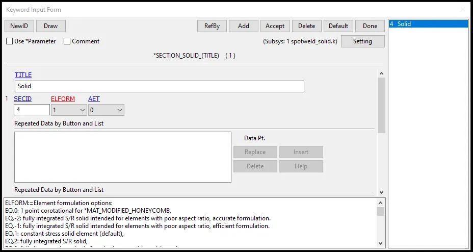
Solid section with type 1ELFORM for spot weld elements is assigned to the solid elements i.e. spot weld elements in case 2.
- Initial velocity of 13.89 m/s in negative X-direction is assigned to the all elements.
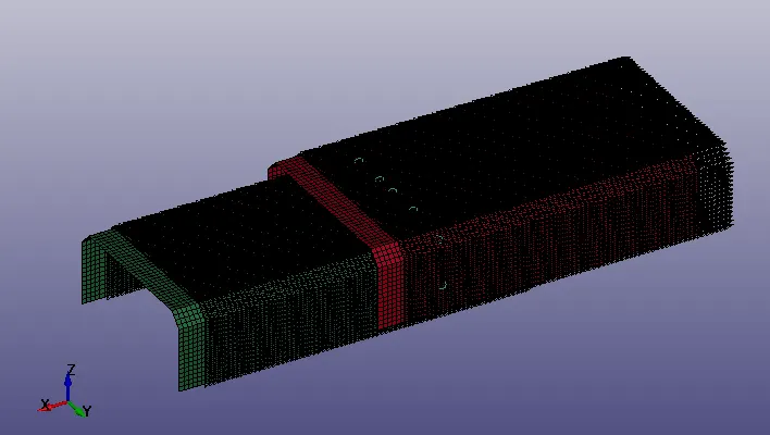
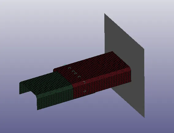
- Rigid wall with 15mm separation from the model is created as shown below.
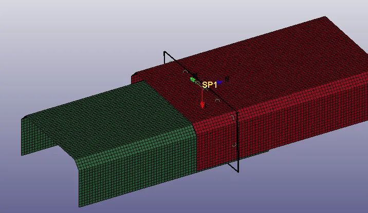
- Cross section plane, nodes and elements are opted for respective output data in the database keywords.
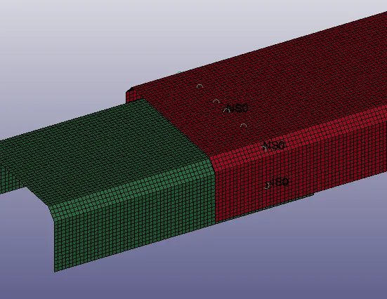
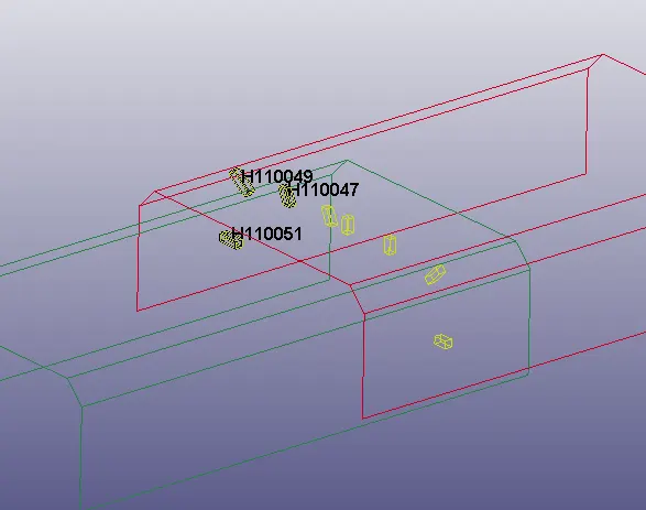
- Suitable output requests are written to extract the required result data. 0.5 ms time step is given to all output requests.
- Control cards such as energy, hourglass and termination are defined accordingly. Termination time of 20ms is given for the simulation.
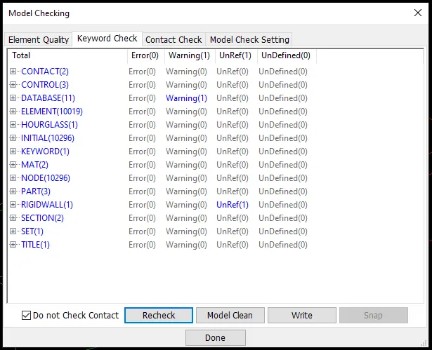
- The model is checked and simulation is carried out.
Solution:
The both cases are successfully simulated using LS manager with normal termination.
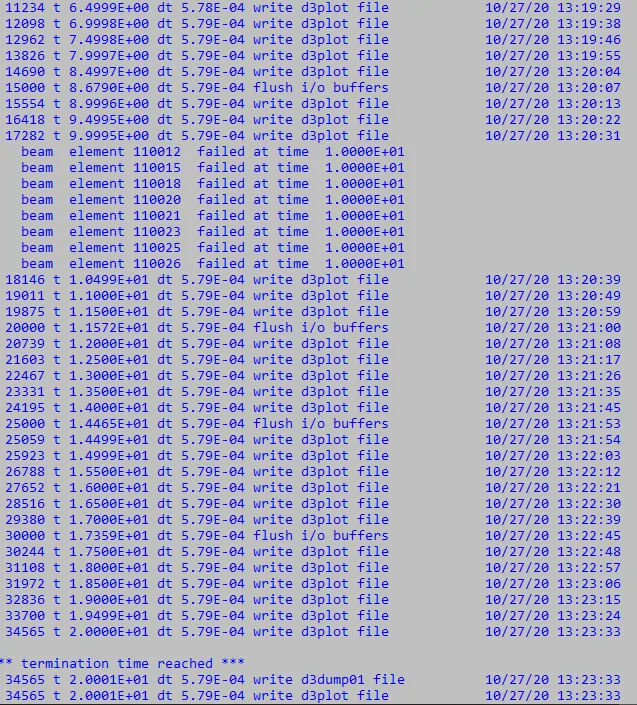
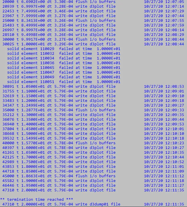
The beam and solid spot welds in both cases are observed to be deleted according to the failure definition with time based failure.
Result:
- Von mises stress
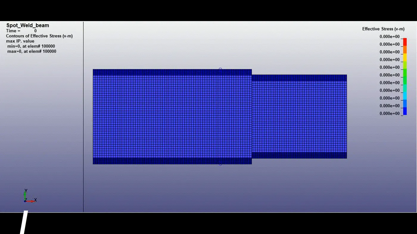
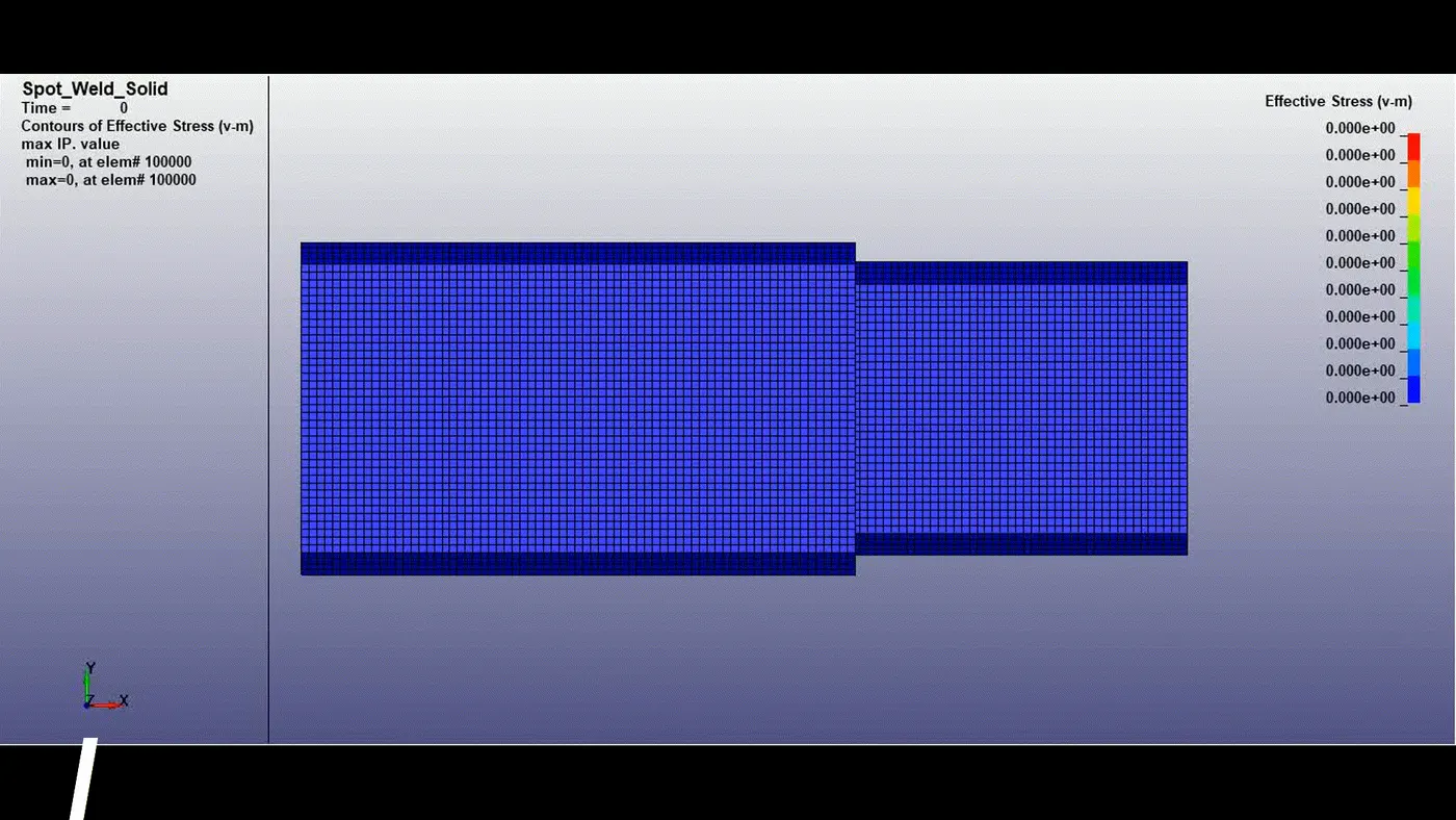
From both cases it can be seen that due to symmetric case setup, the response is also symmetric about XZ plane. Model in both cases bounce back from the rigid wall and model in case 2 moves with less velocity. The stress is majorly developed at the spot weld connected elements in both cases.
- Spot weld forces
Axial forces-
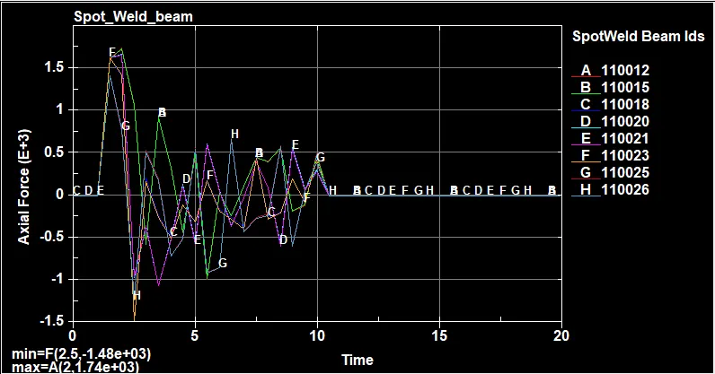
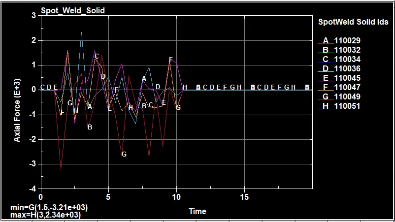
Beam elements being connected to single node will have simple load types acting on it but in case of solid spotwelds being connected to four different nodes at each end, they can experience both tension and compression over its cross section.
Shear forces-
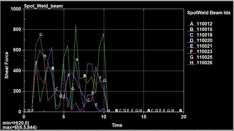
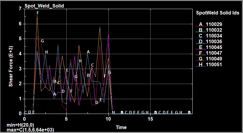
Beam elements are connected to a single node while solid elements are connected to shell elements and they include forces from four nodes, hence from both plots, it can be seen that solid elements experience maximum tensile, compressive and shear forces.
And also it can be seen that, each spot weld element in both cases experience different force at half of the termination time. So it is difficult to calibrate the spot weld card according to force constraints such that all spot weld elements fail at same time. Hence, time based failure approach is preferred here.
- Cross sectional forces
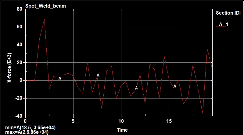
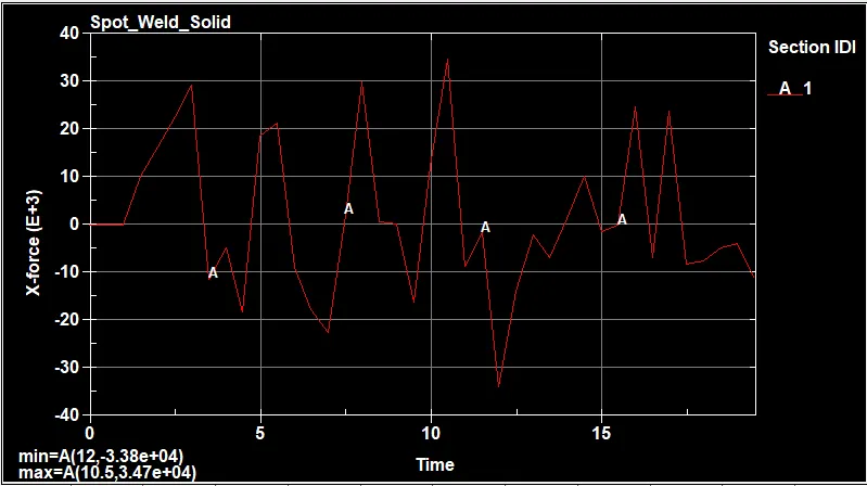
X- force passing through the given cross section is maximum of 6860 N at 2.6ms in case 1 while minimum of -3380N at 12ms in case 2.
- Nodal data
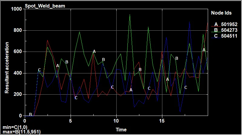
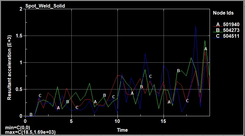
In both cases, the model moves with uniform velocity till approximately 1ms and acceleration increases. From the animations, we can see model in case 2 moves very slow after crash compared to case 1 and this shows the model decelerates very fast in case 2 and it can be validated that the magnitude of deceleration value is more in case 2 from the plots.
- Energy plots
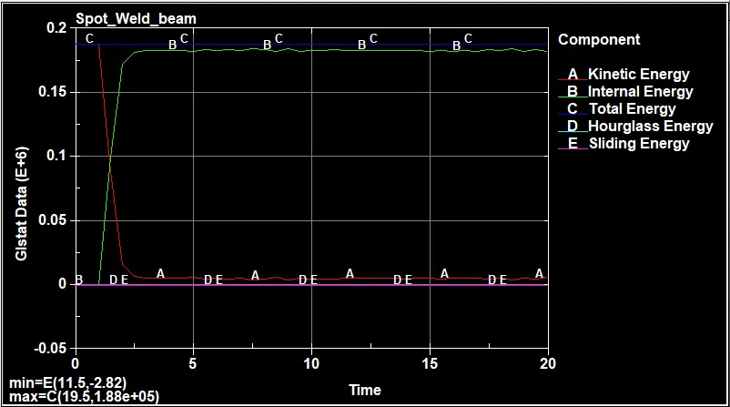
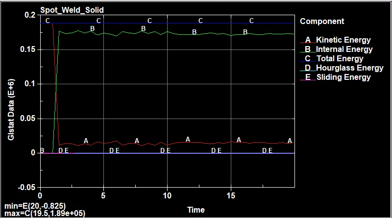
The kinetic energy available at start is converted into the internal energy and thus decreasing the kinetic energy in both cases. The hourglass energy in both cases is considerably controlled and it is observed that considerably zero amount of sliding energy is observed.
Conclusion:
Spot weld modeling with both beams and solid elements are done and successfully simulated. The results from the animation and plots are validated in both cases.