Week 1 Stress Concentration on a Plate with hole
Aim:
Design a plate with required hole definitions and apply load conditions and run the structural analysis.
Procedure:
- Start a new project with static structural analysis as the analysis system in the ANSYS workbench. The standard material with structural steel as the material is used.
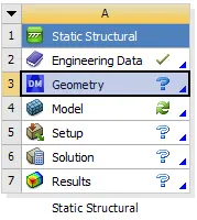
Project flow is as follows;
Material definition > Geometry (model creation) > Mesh generation > Model setup (Set boundary conditions and apply load) > Solve for the model > View and validate results.
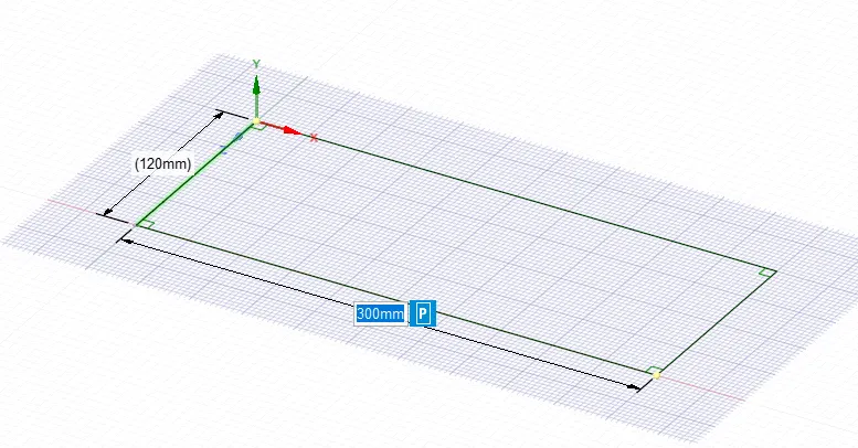
- New geometry is created as per requirement in the SpaceClaim interface.
Case 1:
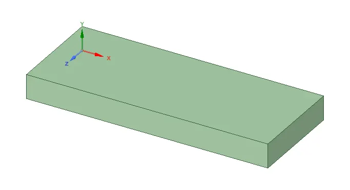
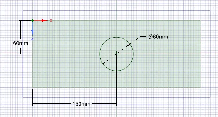
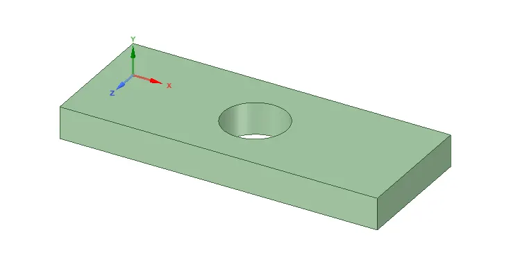
A plate of length 300mm and a width of 120mm of 30mm thick is developed in SpaceClaim. A hole of diameter 60mm at the centre of the plate is placed.
Case 2:
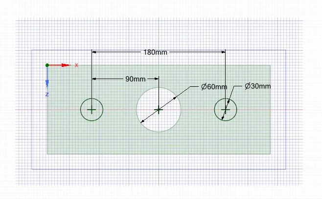
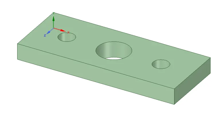
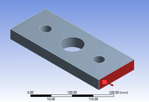
A plate of length 300mm and a width of 120mm of 30mm thick is developed in SpaceClaim. A hole of diameter 60mm at the centre of the plate is placed. Another set of holes of 30mm diameter on either side of the centre hole is created.
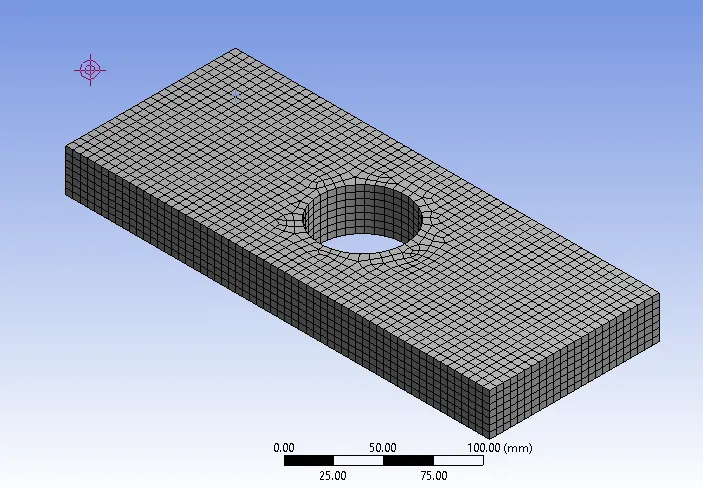
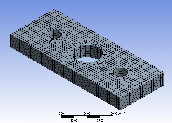
- A mesh is generated from the mechanical module of the structural analysis, with an element size of 5mm.
Case 1: Total elements = 9359, No.of nodes = 43747
Case 2: Total elents = 9065, No. Of nodes = 42829
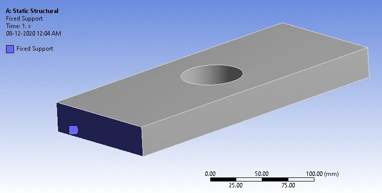
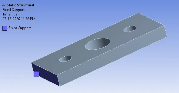
- Boundary conditions are defined according to the requirement. The back face of the plate is fixed, With this fixed support boundary condition to prevent geometry from moving or deforming.
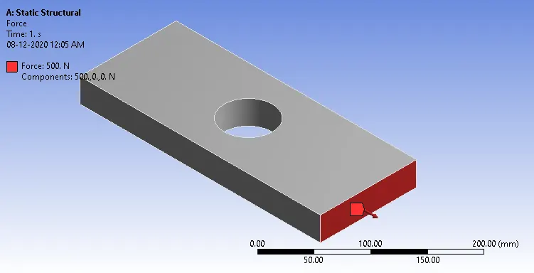
- Load of force 500N is applied on the other face of the plate and the force is distributed across the geometry along the given force vector.
- Both cases are solved with the structural analysis system.
- Required results like total deformation and equivalent stress are requested and they are used for studying the results.
Result:
Case 1:
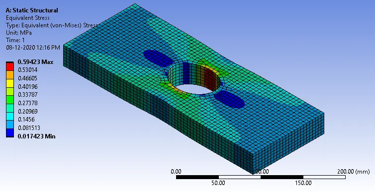
- Maximum amount of stress is observed at the walls of the centre hole with the value of 0.59423MPa.
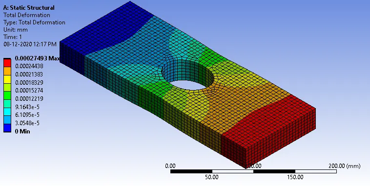
- Highest amount of the deformation in the model is observed near the force acting face. Maximum value of the total deformation is observed to be 2.7493*10-4mm
Case 2:
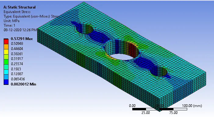
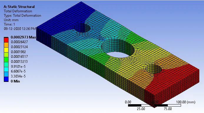
- Maximum amount of stress is observed at the same area as previous case i.e. at the walls of the centre hole with the value of 0.5729MPa.
- Similar to the previous case, highest amount of the deformation is observed near the force acting face and maximum value of total deformation is observed to be 2.973*10-4mm.
Conclusions:
- With extra holes on the either side of the centre hole in case 2, the stress is well distributed throughout the plate and thus decrease the stress concentration at the walls of the centre hole. But in case 1, the stress is being concentrated at the walls of the centre hole and comparatively less distributed across the plate.
- With the same amount of the force being applied in both cases, the model 2 undergoes more deformation compared to the model 1.
- Even though stress being well distributed, the model 2 undergoes more deformation and more likely to undergo plastic strain and thus resulting in undesirable shape. Unless stress is in the allowable range, model 1 is more desirable.
- From manufacturing point of view, model 2 requires additional drilling operations and also occurs in material loss.