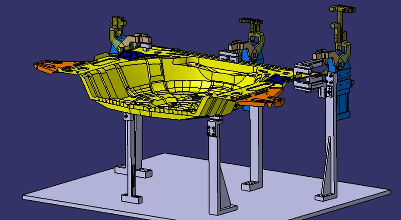
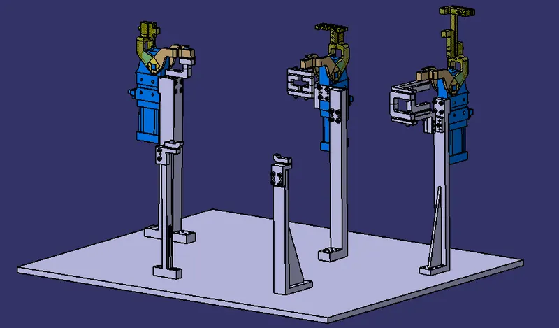
Week 5:- Rest Unit & Clamp Unit Design Challenge
Aim: To design two different types of rest unit and three different types of power clamp units for a certain car panel in CATIA V5.
Clamp unit:
- A tool called a clamp unit uses NC blocks, mylars, or a rest to clamp or hold a vehicle panel while employing a pneumatic cylinder.
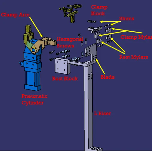
- The standard components of a clamp unit are a clamp arm, finger, a rest or backup, an L-block, shims, a riser, and pneumatic cylinders.
- When developing a clamp unit, clamping force should be considered.
Rest unit
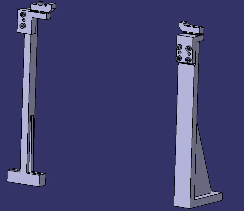
- The automobile panel is supported by a rest unit, which also resists the finger's clamping force using rest mylars and clamps the car panel.
- Riser, shim packs, and rest mylars make up the rest unit.
- When creating a rest unit, holding force should be considered.
- The rest unit and clamp unit are integrated primarily to minimize extra parts, to lighten the load, and to lower the fixture's cost.
Clamp unit types:
- Power clamp unit.
- Swivel cylinder clamp.
Clamp & rest unit's purpose:
Clamping tools are designed to safely keep the workpiece in place while without impeding productivity. Therefore, compact measurements and high clamping forces are the most crucial characteristics for a clamping instrument. Clamps also come with mechanical transmission gear sets because of this.
Clamp & rest unit forces:
Some forces that act in a clamp unit for clamping purposes are taken into consideration when designing a clamp unit.
These forces are present in clamp units:
- Force used to clamp.
- Holding force.
Holding force and clamping force are not the same.
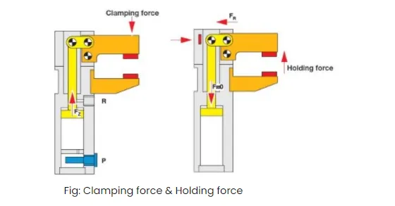
Clamping force: When performing gripping or clamping operations, the driving mechanism exerts force on the workpiece through the clamp arm.
Holding Force: The greatest force that the workpiece can sustain when applied to the gripper/clamp arm after locking the knee-lever without damaging the machine is referred to as holding force.
- Therefore, special consideration must be given to the maximum holding force in some situations, such as when the component may deform during the production process (welding, bonding), or if the clamp arm is utilized as a permanent stop.
- The mechanism, the clamp arm, or the bearing position will unavoidably be destroyed if the holding force indicated in the technical specifications is exceeded.
Principal Locating Points (PLP):
- Principle locating points are the points that are utilized to precisely locate the panel sub-assemblies in order to preserve the assembly's shape.
- Due to stamping processes, the panel has several holes that are not correct. Consequently, the drawings define the PLP.
- The PLP holes need to be precise.
Clamp Plan:
The information on the location of pins, rest units, clamp units, dumps, etc. is provided by the clamp plan.
It is a crucial piece of client feedback. It is not recommended to alter the clamp plan or position without consulting customers.
By specifying a set of coordinates in a certain location, it provides specific information about the precise location of the clamping units.
Formula & calculation: Power clamp cylinder
A clamping force operates at each mylar's end.
Holding Force:
- For this project, the thickness of the panel is reported to be 1mm.
- Since the child parts join below the main panel, the thickness of the sheet metal in the graph below, which will be used to choose the cylinder based on its bore.
- The outreach of the clamp arm may be determined by measuring the distance between the pivot center of the cylinder and the center of the clamping mylars
Clamping Force:
Clamping force (Fs) = 48 x s³ = Force in Newton
In this project, we consider the sheet thickness as 2mm so analytically the clamping force will be,
Clamping force (Fs) = 48 x 2³ = 48 x 8 = 384 =Force in Newton
Clamping force (Fs) = 384 N (Analytically)
Materials used:
The materials used for mylars, clamp arms, shim blocks, blades, and risers are generally:
- Mylars: made of polytetrafluorethylene (PTFE), UHMW, Nylon66, PP, and Teflon. The A class panel or B class panel will decide on the clamp block and rest block materials.
- Teflon is used extensively in exterior panels.
- Steel is instead utilized after being heat-treated.
- Blocks made of aluminum are occasionally used.
- SAE 4140 or SAE 1045 for the clamp arm.
- Shims/spacers include S.A.E. 1010 CRS full hard, S.A.E. 1010 full hard cold rolled strip steel, S.A.E. 1020 HRS, etc.
- Shim block: Stainless steel of types 303 or 304, NM Stainless, STEEL ASTM A-36, etc.
- Blade: ASTM A-36 steel, etc.
- Riser: ASTM A-36 steel, etc.
Clamp unit Parts
Finger: The finger is an NC block that is attached to the cylinder's clamp arm. and will push the vehicle panel in the direction of the rest, holding the car panel in place.
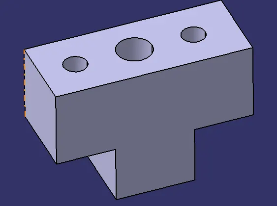
Rest: A rest is an NC block that is fastened to the unit and supports the automobile panel while also preventing the finger from gripping it with its force.
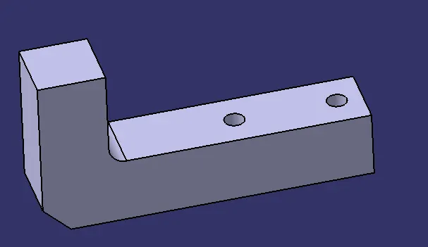
Clamp arm: All moving elements are fastened to the clamp arm, which is a component. In general, clamp arms are offered dependent on the arm's location.
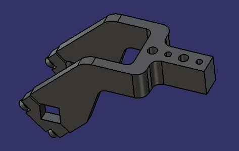
Clamping/Power Cylinder: The clamp cylinder is a pneumatic device that uses pressurized air (5 bar pressure is the industry standard for clamping automotive components). The components fixed to the clamp arm are opened and closed using the clamp cylinder.
- Clamp cylinders are purchased components. Manufacturers include Steelsmith, Tunkers, Zytran, Destaco, and Festo.
- Typically, clamp cylinders have bore capacities of 40, 50, 63, and 80. (Choose based on the graph of sheet thickness vs. outreach)
- Open up to 135 degrees for attaching a horizontal clamp.
- Open up to 105 degrees for attaching a vertical clamp.
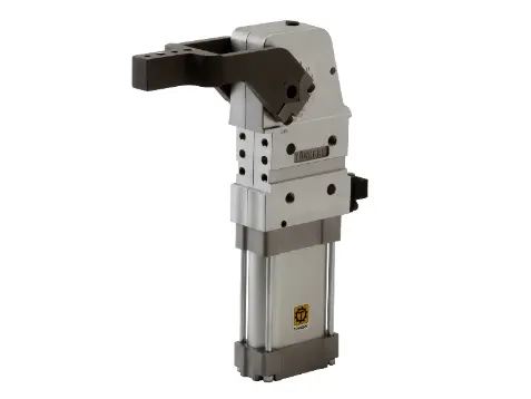
Shims: We provide shim packs in order to accurately place the pin in the hole of the appropriate panel due to variations in the dimension caused by Man, Machine, or Materials.
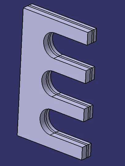
Blade: It allows the freedom to utilize the same riser for various hole location heights.
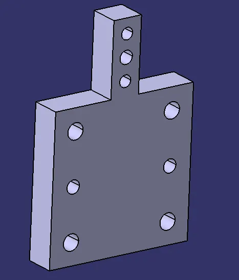
Riser: It is a part that is attached to the base and is used to support every other part.
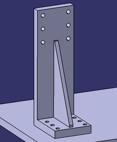
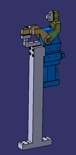
Clamp Unit 1
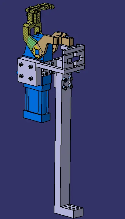
Clamp Unit 2
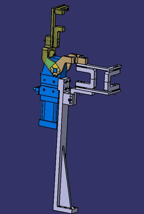
Clamp Unit 3
Rest Units
Final Assembly With Welding component