Week 7:- Base Unit Design Challenges 1
- Base Unit and its parts
A base unit is designed to house all the tool's other components, such as the clamp unit, pin unit, rest unit, etc. Other elements required for a tool, such as a pneumatic valve box and a cable route, will also be installed on a base unit. Additionally, the base unit mounts elements such as the valve bank, junction box, eye bolts, and cable Trunking path.
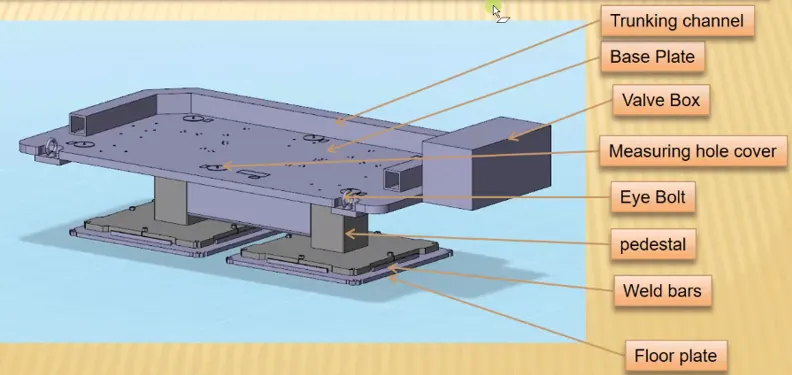
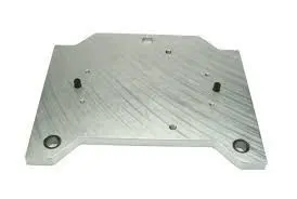
- Base Plate: A flat supporting plate or frame at the bottom of a column that helps to spread out the weight of the column and promote stability. The base plate has several mounting holes drilled into it for the clamp unit, pin unit, and other components. Base plates are machined steel or aluminum plates that range in thickness from 25 to 40 mm and are used to install various units such as rest units, clamp units, pin units, and so forth.
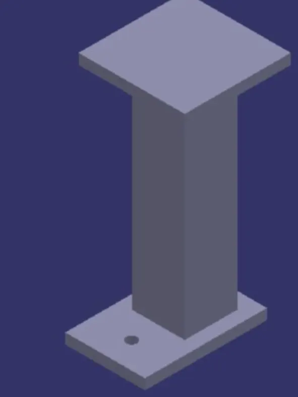
- Pedestal: The base plate and the floor plate are connected by a pedestal, which is a component or assembly (welded construction). Depending on the size and height of the fixture, the pedestal may be a standard part or a custom element. Standard pedestals come in a variety of heights. Additionally, pedestals come in a variety of slopes. The number of pedestals for a fixture might vary depending on the size of the base plate for load distribution.
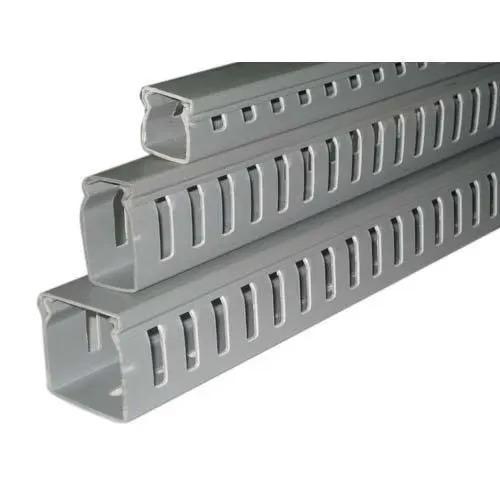
- Trunking Channel:A duct called a Trunking channel is used to transport all the wires and pipes needed for the tool's electrical and pneumatic connections. It is only a few millimeters thick.
- Valve Box: All the valves for the pneumatic units are included in the valve box, which is a standard part. The box containing various solenoid valves is known as a valve box. The pneumatic fittings operate on the air pressure that is supplied to them. So, this valve box is used to organize the air pressure intake and outflow. The pressure inlet cables connecting to the pneumatic components of the fixture are all included in the Trunking channel, which guards against damage while operation is happening.
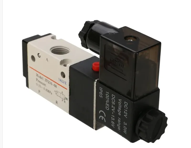
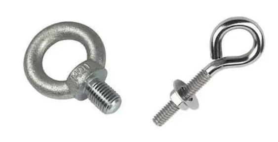
Solenoid valve - Eye Bolt: Eye Bolts are the bolts that are inserted with hooks to raise the fixture for transportation.
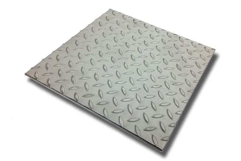
- Floor Plate: The floor plates are fastened to the subfloor with hexagonal bolts. Foundation plates are another name for floor plates. The distance between the pedestal base plate and the floor plate is 10mm. Using leveling bolts, this gap is utilized to level the whole tool. The placements are set permanently using weld bars. Steel plates called weld bars go along the pedestal's base plate's sides.
2. Designing Base Unit
- Working Height: This depends on the kind of welding fixture—manual or automated. For manual fixtures, we must consider the working height of 500-1100 mm; this depends on the worker's working height and the applicable national standards (in certain countries, such as the US and Japan, human height might be higher or lower). We may build a base structure that is 100 mm to 250 mm tall if the base plate has a tubular structure soldered beneath it. In this situation, we will need to install an extra leg structure with a top and a plate that is welded to a tube in order to achieve the working welding height. Designing the unit height and base top height comes after thoroughly studying the gun's ergonomics.
- Eyebolt Size: Prior to fabrication and handling, it is crucial to understand how large a base plate or bigger base welded design will be handled. For lifting holes on the base plate, eye bolt sizes are chosen based on weight.4 eye bolts are typically provided. The placement of the eye bolt must also consider the fact that the rope or belts used to move the entire fixture or the structure will not damage any rest, clamp, or location components.
- Plate Thickness: Few OEMs (like BMW) advise using 40mm or 50mm thick foundation plates for the child component assemblies. Even though 40/50mm plate creates relatively heavy structures.
To ensure that the fixture deflects as little as possible, the base unit of the fixture must be sturdy enough. Weight should be added in the fixture's base unit to minimize noise and vibration.
Simple components may be used to construct the base unit, allowing additional units to be screwed or welded together as needed. It is possible to fuse the various parts of the fixture that will always be part of the fixture. The screws can be used to hold parts that need to be changed often.
The base unit should be parallel to the floor, and a height-adjustable mechanism should be provided to allow for this.
- Weld framework or a base plate: Whether we require a fabricated foundation or only a plate depends on the component size & weight of the overall units. Fabricated bases constructed of square or rectangular tubes with plates are often employed.
- Measuring Holes: In order to define the plane, we would need three measuring holes. Most OEMs make four dowel holes at each of the four corners and place a little aluminum plate with the dowel holes' X, Y, and Z coordinates marked on it. Dowel holes should be 500 mm apart if the base length is too long.
3. Dump Unit
- Dump units are used when mounting conventional units like as clamp units, pin units, etc. is not possible due to geometrical constraints.
- Due to space restrictions, dump units are difficult to design since it is necessary to fit all the pieces into the limited area.
- To accomplish the clamping and unclamping of the automobile panel, it has a dump cylinder.
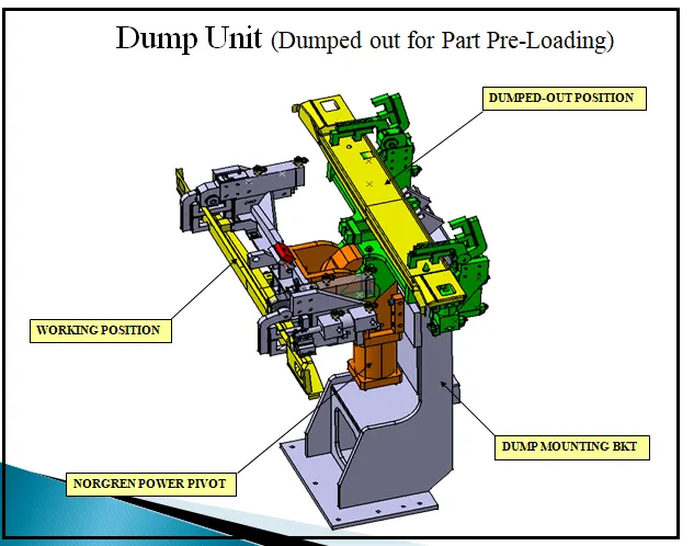
4. Design considerations of Dump Unit
- When standard units like clamp units, pin units, etc. cannot be utilized because of space restrictions, dump units are employed. The design elements should be compact while still performing their tasks well.
- It maintains the dump cylinder, which will be the bulkier component of the entire unit. The riser and blade should be strong enough to support the weight of the cylinder and the entire unit.
- The parts should be constructed with the unit's open state in mind. The portion should not fall onto the other unit while the unit is open.
5. Slide Unit
Slide units are positioning devices used to set up fixtures, weld guns, Base Unit, and Robots for subsequent operations.
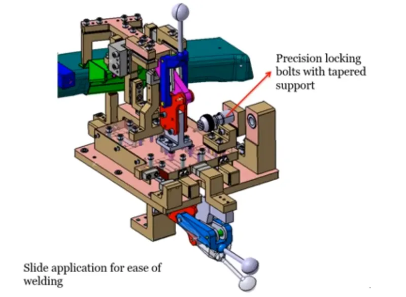
Based on Guideways used slide units can be classified into
- Hardened guide ways.
- LM guide way
Slide units can be classified into three types on the base of prime mover used:
- Manual slides
- Hydraulic / Pneumatic slides
- CNC slides
It may also be classified depending on applications:
- Horizontal slides
- Vertical slides
- Angular slides
The parts of slide units include bellows or rail protection covers, two proximity switches or reed switches for detecting the two end positions, linear cylinder, front and rear stoppers, front and rear shock absorbers, and LM guides.
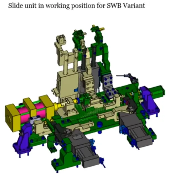
6.Design considerations of Slide Unit
- For sliding unit applications, center trunnion/rear clevis mounted cylinders are excellent because they allow for some float to absorb misalignment.
- Validation of cylinder and LM guides for load and stroke.
- Consider a mechanical hard stop for both extended and retracted conditions.
- Slide must be secured with a safety pin during transit in the retracted position.
- For both the forward and retracted state, a 10 mm reverse stroke should be considered.
- The LM guide rail length should be uniform and greater than the actual stroke.
- A shock absorber should be utilized in both instances.
- The proximity switch will detect the two end limits outside.
- The shock absorber must be positioned so that, at midstride or within +/- 5 degrees, it is perpendicular to the pivot.