Control Logic for Washing Machine and Gear Shift
Aim: To implement control logic of a “washing machine” using Stateflow.
Objective:
- To activate the system if power supply is available.
- To stop the process if there is no water supply.
- To complete all the process and turn ON the LED.
Introduction:
The process includes soaking, washing, rinsing, and drying. During every cycle the machine fill-in the fresh water, and drained out the dirty water.
The first cycle is to turn ON the machine and to allow water to enter into it and soak the clothes for 200 seconds.
The next cycle is known as the washing cycle when the machine takes the detergent and cleans the clothes thoroughly from moving one direction to the other direction for 100 seconds. In the third cycle, the soapy water is drained and fresh water is added, which remove the soaps residue from the clothes for 20 seconds.
In the last cycle, the soapy water is then drained, the machine movies quickly and remove all the water from the clothes to dry the clothes for 50 seconds. After all the cycles are complete, the machine will stop according to our simulation model.
Model:
Link to the Model: https://drive.google.com/file/d/1b1rCb2gfWOh8u2G-3xv5m61UU3mN1rdp/view?usp=sharing
STATEFLOW
Explanation:
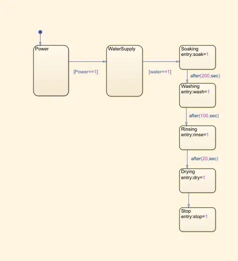
Initially, a Stateflow for washing machine is created using a chart block. Chart is used to implement control logic with finite state machine.
A state is created for Power input to check the power available to the machine/sateflow. Similarly, a state for water supply is created to check the proper supply of water.
For the process involved in the machine, states are created for soaking, after 200s the state is changed to washing, after 100s the state is changed to rinsing and after 20s the state is changed to drying, after drying the state is immediately changed to Stop.
Symbol pane is enabled and the input data, output data and the local data are assigned. In this case, Power and water supply are the input data, soak, wash, rinse, dry are the local data, and Stop is the output data.
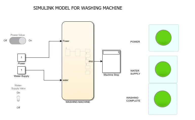
Switches are connected to the inputs of the stateflow through a constant block. Here, slider switch is used for power supply and toggle switch is used for water supply. Switch block toggles the value of the connected block parameter between two values during simulation.
Lamps are connected to the inputs and the output of the stateflow and are set on a panel to view the indications while viewing the stateflow. The Lamp block displays a color indicating the value of the input signal.
Result:
The simulation made to run for 600seconds with power and water supply turned-ON, all the process of washing are complete and are indicated through Lamps.
Conclusion:
We can see that only if the Power supply and the Water supply are ON, the washing process inside the stateflow will take place otherwise the state is returned to first state and the lamps for the inputs will glow.
If all the process are complete the state is returned to the last state and the washing-complete lamp will glow.
GEAR SHIFT:-
Aim: To make a Simulink chart for the “Gear shift” logic.
Objective: To vary the speed while simulation is running and display the gear number.
Introduction:
As your speed increases, you’ll need to change up to another gear.
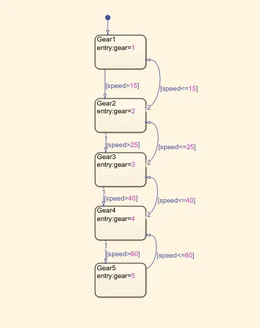
In this model, the gear number is ‘1’ if the speed is between 0-15kmph, ‘2’ between 16-25kmph, ‘3’ between 26-40kmph, ‘4’ between 41-60kmph, ‘5’ above 61kmph.
Model:
Link to the Model: https://drive.google.com/file/d/1lE3No7y7LbEPoojGxZIQPIvKb7M7cT_A/view?usp=sharing
Stateflow
Explanation:
Initially, a Stateflow for gear shift is created using a chart block. Chart is used to implement control logic with finite state machine.
States are created for every gear shift and the required speed range is assigned to each state. Input data and output data of the stateflow are assigned through the symbols pane. Input data being the speed and Gear is the output data to the stateflow.
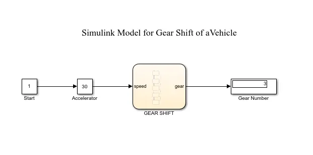
A slider gain is used as an accelerator to vary the speed(input) given to the stateflow. The Slider Gain block performs a scalar gain that can be modified during simulation. A constant block of value 1 is added to give a start to the slider.
The gear number for the given speed is displayed using a Display block.
Results:
The Simulink chart for the “Gear shift” logic is created.
We can see that the gear number at a speed of 30kmph is ‘3’, as shown in the Model.
Conclusion:
As the speed is varied, the gear number keeps on changing according to the range assigned in the stateflow.
The Gear number for every speed range is verified and the gear shift is accurate.