DC Motor Control
Aim: To study the MATLAB model ‘Speed control of a DC motor using BJT H-bridge’.
Objective: To run the MATLAB demo ‘Speed control of a DC motor using BJT H-bridge’ and modify the model such that armature current doesn’t shoot up when motor changes direction from forward to reverse.
Introduction:
Power Electronics refers to the process of controlling the flow of current and voltage and converting it to a form that is suitable for user loads.
Power electronic devices may be used as switches, or as amplifiers. An ideal switch is either open or closed and so dissipates no power; it withstands an applied voltage and passes no current, or passes any amount of current with no voltage drop. Semiconductor devices used as switches can approximate this ideal property and so most power electronic applications rely on switching devices on and off, which makes systems very efficient as very little power is wasted in the switch.
An H-bridge is an arrangement of transistors that allows a circuit full control over a standard electric DC motor. That is, an H-bridge allows a microcontroller, logic chip, or remote control to electronically command the motor to go forward and reverse.
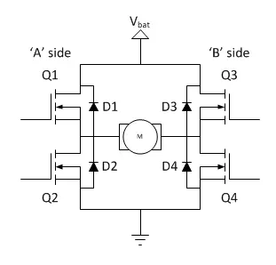
Q1, Q3: These are NPN transistors. They connect the motor to the negative terminal of the battery.
Q2, Q4: These are PNP transistors. They connect the motor to positive terminal of the battery.
D1-D4: Diodes provide a safe path for the motor energy to be dispersed or returned to the battery when the motor is commanded to coast or stop.
Model:
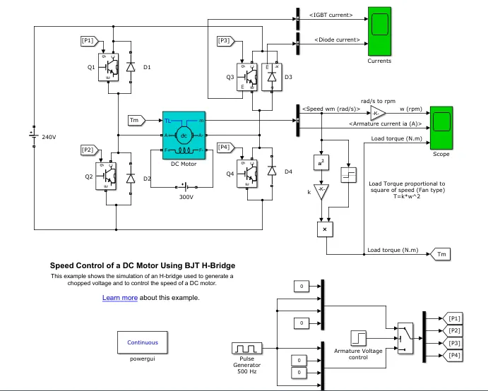
The motor used in this case is a 5HP 240V 750RPM DC motor. Initially, the duty cycle of the model is kept at 75% which is the pulse width of the pulse generator block. The model is made to run for 1 sec and we have to observe whether the armature current is shooting up when the motor changes its direction from forward to reverse.
If the armature current shoots up when the motor changes its direction from forward to reverse, we have to reduce the duty cycle and see that at what duty cycle the armature current doesn’t shoot up.
Results:
When Duty Cycle = 75%,
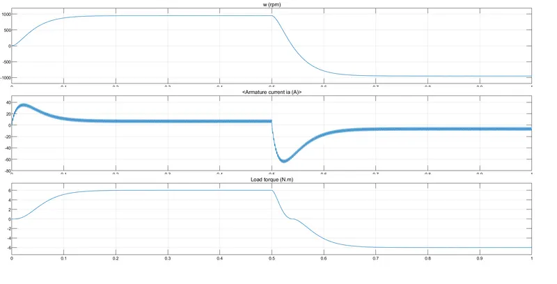
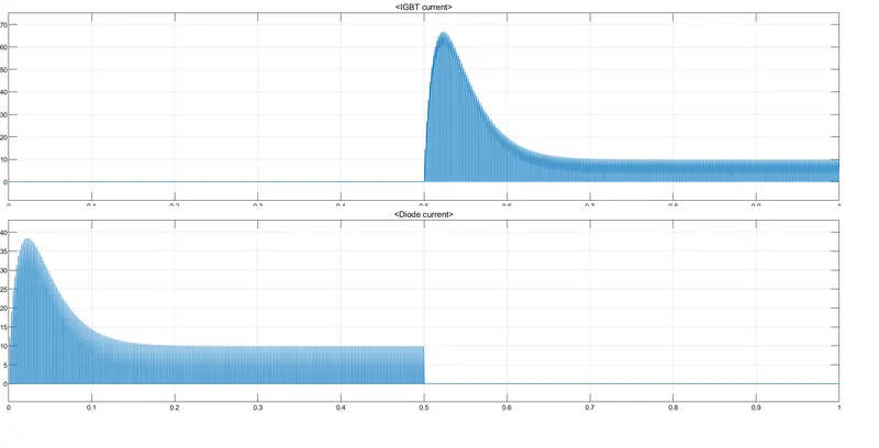
The max. armature current is 37A. After 0.5 sec the motor changes its direction from forward to reverse and the armature current shoots up.
When Duty cycle = 45%,
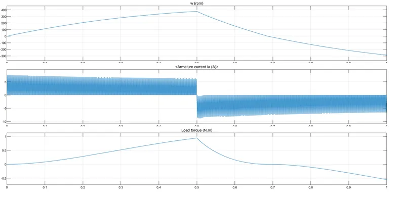
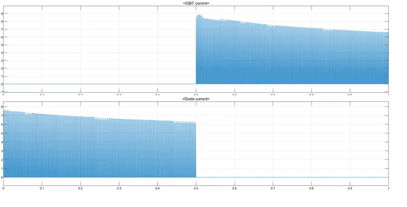
The max. armature current is 7.3A. After 0.5 sec the motor changes its direction from forward to reverse and the armature current doesn’t shoot up.
Conclusion:
The Armature current doesn’t shoot up when the duty cycle of the model is 45% or below during reverse motoring.
DC7 Block:
Aim: To compare the Four-Quadrant Chopper DC Drive (DC7) block with the H-bridge Model.
Objective: To refer to help section of ‘The Four-Quadrant Chopper DC Drive (DC7) block’ and ompare it with H-bridge model.
Introduction:
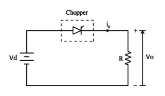
A dc-to-dc converter, also known as dc chopper, is a static device which is used to obtain a variable dc voltage from a constant dc voltage source. Choppers are widely used in
trolley cars, battery-operated vehicles, traction motor control, control of large numbers of dc motors, etc. They are also used as dc voltage regulators.
Choppers are of two types:
(1) Step-down choppers.
(2) Step-up choppers.
In step-down choppers, the output voltage will be less than the input voltage, whereas in step-up choppers output voltage will be more than the input voltage.
The four-quadrant chopper is a chopper which can operate in all the four quadrants. The power can now either from source to load or load to source in this chopper. In the first quadrant, a Class-E chopper acts as a Step-down chopper whereas in the second quadrant behaves as a Step-up chopper. This type of chopper is also known as a Class-E or Type-E chopper.
Model:
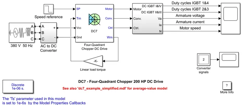
The 200 HP DC motor is separately excited with a constant 150 V DC field voltage source. The armature voltage is provided by an IGBT converter controlled by two PI regulators. The converter is fed by a 515 V DC bus obtained by rectification of a 380 V AC 50 Hz voltage source. In order to limit the DC bus voltage during dynamic braking mode, a braking chopper has been added between the diode rectifier and the DC7 block.
The first regulator is a speed regulator, followed by a current regulator. The speed regulator outputs the armature current reference (in p.u.) used by the current controller in order to obtain the electromagnetic torque needed to reach the desired speed. The speed reference change rate follows acceleration and deceleration ramps in order to avoid sudden reference changes that could cause armature over-current and destabilize the system. The current regulator controls the armature current by computing the appropriate duty ratios of the 5 kHz pulses of the four IGBT devices (Pulse Width Modulation). For proper system behaviour, the instantaneous pulse values of IGBT devices 1 and 4 are opposite to those of IGBT devices 2 and 3. This generates the average armature voltage needed to obtain the desired armature current. In order to limit the amplitude of the current oscillations, a smoothing inductance is placed in series with the armature circuit.
Comparison:
| DC7 Block | H-Bridge Model |
|
|
EV Model using DC7 Block:
Aim: To create an EV model using DC7 Block.
Objective: To refer to the DC7 block and make an EV model using it.
Model:
Speed Torque Characteristics:
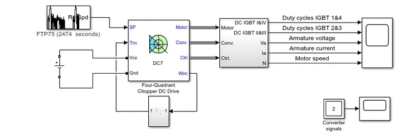
Here, the speed reference of the DC7 block is replaced by a drive cycle block which provides the drive cycle inputs to the Chopper. The power source to this is replaced by an DC Voltage source of 400V.
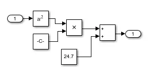
The torque-speed characteristic equation in this case is,
T = 24.7 + (0.0051*ω^2)
A subsystem is created using the above equation and is connected to the speed and torque ports of the Chopper DC Drive block.
Results:
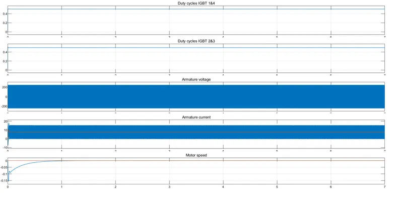
The EV Model is created using DC7 block and is made to run at FTP75 drive cycle and the following plot is obtained.