Week-6 Challenge: EV Drivetrain
Aim: To study the power converter circuits that are employed in electric and hybrid electric vehicle.
Introduction:
Power Electronics refers to the process of controlling the flow of current and voltage and converting it to a form that is suitable for user loads.
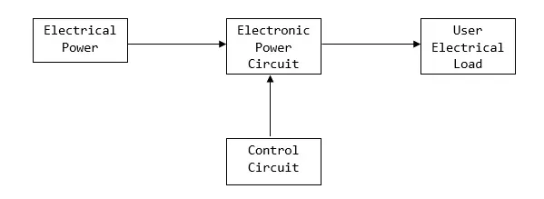
Power electronic devices may be used as switches, or as amplifiers. An ideal switch is either open or closed and so dissipates no power; it withstands an applied voltage and passes no current, or passes any amount of current with no voltage drop. Semiconductor devices used as switches can approximate this ideal property and so most power electronic applications rely on switching devices on and off, which makes systems very efficient as very little power is wasted in the switch.
Explanation:
There are mainly four types of Power Converter circuits that are used in Electric Vehicles and Hybrid Electric Vehicles,
- AC to DC Power Converter (Rectifier)
A rectifier is an electrical device that converts Alternating Current, which periodically reverses direction, to Direct Current(DC), which flows in only one direction.
An EV Charger converts Alternating Current from the supply to Direct Current to the battery pack.
- DC to AC Power Converter (Inverter)
A power inverter, or inverter, is a Power Electronic device or circuitry that changes Direct Current (DC) to Alternating Current (AC). The resulting AC frequency obtained depends on the particular device employed.
Direct current from the battery pack of an EV is converted to Alternating Current to the induction Motor of the EV.
- DC to DC Power Converter
A DC-to-DC converter is an Electronic circuit or electromechanical device that converts a source of direct current(DC) from one voltage level to another. It is a type of electric power converter. Power levels range from very low (small batteries) to very high (high-voltage power transmission).
High voltage Direct Current from battery pack of EV are converted to low Voltage DC to auxillary system of the EV by the Chopper. Using Step-up DC converter, the low voltage DC can be converted to high voltage DC.
- AC to AC Power Converter
A solid-state AC-to-AC converter converts an AC waveform to another AC waveform, where the output voltage and frequency can be set arbitrarily.
Generally, these type of converters are not used in an Electric Vehicle as they convert one voltage type to another.
Conclusion:
We see that all types of Power Converters are required by an Hybrid and Pure Electric Vehicles. Hence, all Power Converters find application in Electric Vehicles.
Steady state of an EV:
Aim: To find the steady state of the given Electric Vehicle.
Calculation:
Given Parameters of the electric vehicle are,
Motor and Controller Parameters:
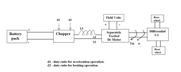
Rated Armature voltage= 72 V
Rated armature current= 400 A
Ra= 0.5Ω,
KΦ= 0.7 Volt second
Chopper Switching frequency= 400 Hz
Duty Cycle = 70%
The duty ratio for acceleration operation is 'd1' and for the braking operation the duty ratio is 'd2'.
Let us consider,
Mass = 1000Kg
Frontal area = 2 m^2
Drag Coefficient (C_d) = 0.2
Rolling resistance coefficient (µ_rr) = 0.009
Gear ratio(G) = 1
Density = 1.1614 kg/m^3
Radius of the Wheel = 11 inches = 0.28m
Rolling Resistance force,
Frr = µ_rr * m * g
Frr = 0.009 * 1000 * 9.81
Frr = 88.29 N
Drag force,
Fad = 0.5 * Rho * A * C_d * v^2
Fad = 0.5 * 1.1614 * 2 * 0.2 * v^2
Fad = 0.232 * ω^2 * R^2
Fad = 0.232 * ω^2 * 0.28^2
Fad = 0.0182 * ω^2
Total Traction Force,
Fte = Frr + Fad
Fte = 88.29 + [0.0182* ω^2] …….(1)
Also,
Fte = (G*T)/R …….(2).
Equating (1) and (2),
(G*T)/R = 88.29 + [0.0182* ω^2]
Torque, T_v = 24.72 + [0.0051* ω^2]
This is same as the given equation for speed-torque characteristics.
For Motor,
Speed-Torque relation is given by,
ω = (V/ KΦ) – (T_m*Ra/( KΦ^2))
T_m = (V* KΦ/Ra) – (ω*( KΦ^2)/Ra)
Voltage (duty cycle = 70%)
V = 72 * 0.7 = 50.4V
Motor Torque, T_m = (50.4*0.7/0.5) – (ω*(0.7^2)/0.5)
T_m = 70.56 – (0.98*ω)
Steady-state Condition,
T_v = T_m
24.72 + [0.0051* ω^2] = 70.56 – (0.98*ω)
Angular velocity,
ω = 38.9 rad/sec
Result:
The Steady State speed for the given Electric Vehicle is 38.9 rad/sec.
Induction vs DC Brushless Motor:
Aim : To explain Induction Versus DC Brushless Motors article by Wally-Rippel.
Objective: To refer to the blog, Induction Versus DC brushless motors by Wally Rippel, Tesla and explain in brief about Author’s perspective.
Explanation:
In DC Brushless motors,
The rotor includes two or more permanent magnets that generate a DC magnetic field. This magnetic field enters the stator core and interacts with currents flowing within the windings to produce a torque interaction between the rotor and stator.
The DC Brushless motor generates less heat. Rotor cooling is easier and peak point efficiency is generally higher for this drive.
When maximum torque is required, especially at low speeds, the magnetic field strength (B) should be maximum so that inverter and motor currents are maintained at their lowest possible values.
The current losses are more here and can be reduced. But , it is very difficult to control the strength of the magnetic field.
In this type of motor. as machine size grows, the magnetic losses increase proportionately and part load efficiency drops.
In Induction Motors,
The induction rotor has no magnets – just stacked steel laminations with buried peripheral conductors that form a “shorted structure.” Currents flowing in the stator windings produce a rotating magnetic field that enters the rotor.
The Induction motor generates more heat compared to the DC Brushless motor.
Induction machines don’t have permanent magnets and B fields are “adjustable,” since B is proportionate to V/f (voltage to frequency). This means that at light loads the inverter can reduce voltage such that magnetic losses are reduced and efficiency is maximized.
In this type of motor. as machine size grows, losses do not necessarily grow.
Conclusion:
DC Brushless motors are more expensive compared to the Induction motor. But, the controlling the Brushless DC motor is simple and easy to understand and stability of torque-speed range and over temperature is more difficult with induction than with DC brushless. This makes us to use DC Brushless motor in an HEV instead of Induction motor.
When HEV are made to produce more power through motor, we may require the induction motor as well. In the coming years, we may see induction and DC brushless motor both working together in Hybrid and Pure Electric Vehicles.